Eng-Tips is the largest engineering community on the Internet

Intelligent Work Forums for Engineering Professionals

  • Congratulations waross on being selected by the Tek-Tips community for having the most helpful posts in the forums last week. Way to Go!

Time to discharge a Gravity pipe line section using a Scour Valve 5

Status
Not open for further replies.

Tom24

Civil/Environmental
Dec 11, 2022
3
0
0
NZ
Hi All,

Hoping someone might be able to help me with this problem I've been given.
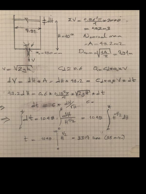
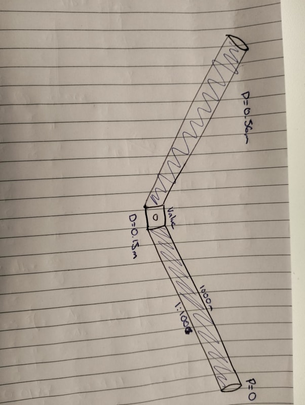
There is a scour valve (150mm diameter) located in the middle of two sections of DN560 PE Pipe. These two sections have a length of 1000m and a slope of 1:100.
In this example I am treating this network as full and separate from any other network. I am assuming the pipe section ends and the valve opening are exposed to the atmosphere thus pressure difference is zero.
The time required to drain the two sections of pipe through the scour valve must be calculated

I've had some trouble finding the correct equations and methods for this problem. I've tried methods using Hazen-Williams equations, I've also using also adapted Bernoulli equation examples that relate to draining a reservoir and relating the change in height(elevation head) to the change in time. This was difficult as the change in the elevation of the water surface was function of the pipe's length and slope.

I've calculated a wide range of answers from hours down 15min.
Looking for some guidance on the correct methods and reasonable assumptions.

Let me know if anyone needs any more information.

Tom
IMG20221212161428_sblz5l.jpg
 
Replies continue below

Recommended for you

I'll answer in this post and hope it doesn't get deleted.

Do you have the CV of the valve?

This is a transient thing so you need to break it down to 4 or more heights of the water above the valve.

I would forget about pressure drop in the main pipe, but add a bit of time, say 10 to 20% to allow some time for this.

It isn't a lot of head to play with (10m/ 1bar) so your answer is only a guide as a small additional friction loss can make a big impact.

IF you've got valve CV then you should be able to calculate flow for different differential head.

If not then try using an orifice calculation using the ID of the vane as the size of the orifice.

But you do need to do it steps of maybe 2m head.

My gut feel for a 90% evacuation is 45 to 60 minutes. The last 10% could take that long again.


Remember - More details = better answers
Also: If you get a response it's polite to respond to it.
 
Hi,
Apply Bernoulli theorem between the top of the pipe(s) and the discharge point. The volume of liquid is equivalent of the volume of the 2 branches. Per analogy this is equivalent to a volume of a reservoir under atmosphere pressure.
About head losses you need to consider the conjunction of the 2 branches, the valve and the discharge to atmosphere and may be bends. I will not consider the head losses of the main lines because the Velocity in the main pipes is much less than the velocity at the discharge.

You must divide the pipe in sections (5 to10) and perform iterative calculation on each section to get access to the velocity. The total time will be the Σ of the individual time to drain each section.
Good luck
Pierre


Attached the set of equations to solve for each section

Energy balance Bernoulli between "1 and 2" 1 free surface of liquid in the main header, with P1 =0
2 discharge point, with P2=0

H1+ P1/(R0*g) +V1^2/(2*g) =H2+ P2/(R0*g) +V2^2/(2*g)+ Hf


Hf = (f*L/d+Σ Ki) *V2^2/2g Hf head losses , L length discharge pipe, d diameter pipe discharge
Σ Ki individual losses (fittings, bend, valve)

P1=P2
V1 <<<< V2 V2-V1 =V2

H1 =H2+V2^2/(2*g)*(1+f*L/d+Σ Ki)

H1-H2 =H
f : function ( Re & ε/d)

f Churchill equation From laminar to turbulent

f=8*((8/Re)^12+((37530/Re)^16+B)^-1.5)^1/12
with
B=(-2.457*ln((7/Re)^0.9+0.27*(ε/d)))^16

to solve

V2^2/(2*g)* (1+f*L/d+Σ Ki) - H =0


methodology
iteration on f until (fn-fn+1)/fn *100 < 1 E-4 f friction factor
to get V2 V2 velocity at the discharge point


H=H1-H2 m H head of liquid

t=V/Qv V volume of each section
Qv= V2* discharge pipe area
 
Hi guys,

Thanks for the help I'll give these methods a go and update you if I run into any problems or my solution and methods are accepted.

Thanks again :)
 
Knowing LittleInch i say this with caution, but i think you may be wrong.
LittleInch said:
If you think of your pipes as a tank 10m high, then I get this to be equivalent to a tank radius 3.95m for both pipes.

PE pipes are normally based on OD so a 560PE pipe is roughly a 500 ID. The c/s area of two 500mm di circles is roughly 710mm dia (I now see your error is possibly a double typo A of 0.710m dia =0.395m2) - roughly 50 seconds which does not sound right!! Maybe LittleInch is correct?

I made the wrong assumption. while the combined diameter of the pipes is 0.71m this does not correlate to the actual volume in the tank. Bernoulli uses head, orifice dia and volume. Total volume in the two lengths of pipe is 392.7m3 (2x 1000m x 500mm dia) so converting this to a 10m high tank (to be able to use the website) is a 10m high tank with a base area of 39.3m2 gives 82 minutes

because these are pipes surely friction losses will come into play?
initial flow is 0.14m3/s so flow in each pipe would be 70l/s which is only 0.1m/s velocity so probably not

 
Hey, I did this very quickly and can easily have made a mistake, but did this in volume and yes took it as ID. It was just to see if I got in the right ball park.

I have ignored the friction losses in the pipe as I think they are negligible.

Remember - More details = better answers
Also: If you get a response it's polite to respond to it.
 
Hi,
The time required to drain 480 m3 of water (2* 1000*.56 with a slope of 1/100) is about 2.0 hours.
Model: vertical tank, height 10 m, Diameter 7.82 m, discharge pipe 2m long, diameter 0.15 m ,Σ ki = 2, absolute rugosity 0.0015 mm
Pierre
 
Tom24 said:
The pipe is denoted as DN560 which means the inside diameter is 560mm

Not so. form Trenchlesspedia web site: "Nominal Diameter is also known as the mean or average outside diameter and is represented by DN. It is neither equal to the inner diameter (ID) nor the outer diameter (OD) of the pipe. Nominal is a word that denotes non-specificity and in this case, identifies the approximate inner diameter with a non-dimensional number.

Pipes having identical nominal diameters can be easily connected or interchanged with each other. Pipes are available in different DN sizes and the DN is used to arrive at the pipe dimensions using standard tables and schedules.

The actual inner diameter of pipes from different manufacturers can deviate by several millimeters and such pipes can be combined if the DN is indicated with reference to standards"

in all the places i have worked PE generally refers to OD with ID changing depending on pressure rating that results in wall thickness changes. The same applies to PVC pipes but here DN is a regional item, here it is normally closer to ID but some countries also refer to OD (eg 100mm id being referred to as 110mm pipe as this is the OD) again if you look at any product tables you will find very few pipes are exactly what they are called.
For your 560PE pipe (assuming it is PE100) here ranges from 533mm ID to 430mm ID at PN20 Definitley something to keep in mind when calculating pipe velocities and head losses

 
Because we do not know the actual ID or roughness of the pipe and we do not know the type of drain valve, calculating an accurate estimate of the draining time is impossible. But we can talk about some principles to follow. Until we have all the information, the tank analogy is about as good as we can get.

The first principle that we all seem to agree on is to break the overall problem into smaller pieces and to calculate the time for step changes in the level. Once the formulas have been resolved, the number of iterations does not make any difference to the amount of work. Copying a row in a spreadsheet down to 10 more rows is not really any less work than copying it to 100 rows so the number of iterations is no longer the issue it was in the slide rule era.

The pressure drop available has to provide for 3 separate losses. These are the friction loss down the DN 560 pipe, the loss through the valve and the acceleration loss (or exit loss). The exit loss is likely to be more significant than the friction in the pipe and I agree with Pierre that Bernoulli effects must be included.

But calculating these 3 separate losses is made more complicated by the fact that there are 2 separate legs to the pipe (even if the layout is symmetrical) while the loss through the valve and the exit are based on the total flow. I believe that a way to simplify this would be to note that the Cv of valves in parallel are additive. A 150 NB gate valve would have a Cv of about 2400 and the flow or pressure drop would be the same if two valves each with a Cv of 1200 was used. This means that we can break the problem into two separate but identical pieces - each containing only 1 of the piping legs and a valve with a Cv of exactly half that of the proposed common valve.

A wrinkle in this method would be that the velocity out of each of these valves would have to be equal to the velocity of the combined flow through a 150 mm valve. So you might end up with a pseudo valve of around 108 mm NB with a Cv of half of that of the original valve. You probably couldn't buy such a valve but it would be useful for modeling the flows.


Katmar Software - AioFlo Pipe Hydraulics

"An undefined problem has an infinite number of solutions"
 
Not sure if this model reduction to a 7.8m vertical tank is correct.
It is possible to write out this drain operation as a differential eqn and solve for H, the vertical height of water column in these 560mm pipes

P - Po = K. rho.v2/2

Express P (pressure at any time t at the inlet to the 6inch pipe run) in terms of H, Po = 1bar abs

v in the 150mm pipe can be written as (dV/dt), the rate of change of water volume in the pipe, and this can in turn, be also written as an expression in H. Think you'll get a first order, 2nd degree, linear DE in H. Solve for H in terms of t.


I looked this post several days ago but could not find time to write ..

The initial discharge velocity at at scour valve exit Vi= SQRT (2gH ) → Vi= 14.0m/s
İnitial discharge Qi= Cd*A0* Vi= 0.6* 0.15*0.15*Pi*14*0.25=0.14 cu-m /sec.

The initial velocity at DN560 pipe

Vpipe= 0.14/(2*0.56*0.56*pi*0.25)=0.28 m/sec. → the friction loss at DN560 pipes can be neglected..

The time required to drain the pipes can be modelled with vertical tank and the can be calculated using integral.

I have hand calculated and pasted below . ( the mass flow alltough negative, i have choosen positive sign and integral from 0 to 10 m)

Pipe_emptying_yqzs30.jpg


Tim was so learned that he could name a
horse in nine languages: so ignorant that he bought a cow to ride on.
(BENJAMIN FRANKLIN )
 
Info I see on the net tells me a scour valve is typically half line size, so a 3inch gate valve with equivalent length 2ft translates to 2.(6/3)^5 = 64 ft of 6inch pipe.
2 pipe reductions (550mmx150mm) operating in parallel amounts to L = 4.5 ft ( 1/L = 1/L1 + 1/L2)
Say 1 90deg bend, 6inch, L = 11ft
1 tee, flow through branch,6inch, L = 32 ft
Sum = 110ft of 6inch line, which amounts to resistance coeff K = 3.5, Fanning f = 0.0039
Single tank equivalent dia = 7.8m, height = 10m
t = 2282.(H1^0.5 - H2^0.5) - expression is similar to that derived by @hturtak (simple linear first order DE) - note most of the resistance to flow is from the 6inch drain line
Time taken to drain = 7216sec = 2.0hours
DE is -∫H^(-1/2).dH = ((2g/K)^0.5)*((Dp/Dt)^2). ∫dt, where Dp=0.15m, Dt=7.8m

Also should check that line velocity is not too high at the start with the scour valve full open, else you could break the pipe supports with high momentum forces if rho-V2 exceeds 200e3 in SI units, so keep to say rho-V2 = 150e3, which translates to v = 12m/sec. Flow would most likely be cavitating at the scour valve, with bubbles collapsing at valve exit. I get start velocity through 6inch line = 7.6m/sec - ok, while corresponding start velocity in each 550mm pipe is 0.3m/sec.
 
@georgeverghese - this seems to be the most realistic answer so far. Should the K value be increased by 1.0 to allow for the exit loss (acceleration), or am I missing something?

Katmar Software - AioFlo Pipe Hydraulics

"An undefined problem has an infinite number of solutions"
 
@katmar, If you mean the exit from the 6inch line to the atm, I've not included this, since the exiting jetstream has more or less the same velocity profile as just before it leaves the 6inch line.
I've listed out the contributors to the total K, so one can adjust the value of K to suit actual pipe run configuration at site, and get a new value for t. Some 50% of this total K is from the assumed reduced bore gate / scour valve. In comparison, a 6inch gate valve L is only some 4feet.
 
@katmar, Yes, K should be increased by 1.0, since the exit stream kinetic energy (amounting to (ρv2)/2) is derived from the pressure head of the stationary liquid in the DN550 pipes. So K=3.5+1=4.5, and t becomes 8182secs = 2.27hours.
 
Status
Not open for further replies.
Back
Top