Continue to Site

Eng-Tips is the largest engineering community on the Internet

Intelligent Work Forums for Engineering Professionals

  • Congratulations GregLocock on being selected by the Eng-Tips community for having the most helpful posts in the forums last week. Way to Go!

tips on creating a drawing of an existing piping system 2

Status
Not open for further replies.

kacarrol

Mechanical
Apr 14, 2010
206
Myself and a couple of staff have to make a flow diagram of an existing piping system (low pressure water, nothing ASME etc). It is a rather large and convoluted system as it has been tapped into and changed a number of times over the years and spreads through out an area of approximately 120 feet x 250 feet, up to three levels high in some places. Most of the pipe is exposed but they are broken up by walls and some is hard to see as there are other pipes in the way. There are other unmarked pipes mixed in too (steam heating, ASME designed piping etc).

I have some 3D and some isometric drawings of the ASME piping.

I need approximate length (say +/-10 feet), pipe diameter and water meter locations marked on this flow diagram. I have the water meter locations.

I have experience on the piping stress and design side of piping but I've only once had to pretty much start from scratch and recover a piping system on to paper, that was almost two decades ago and much less complicated, my staff have very limited piping drafting experience and no experience in trying to recover a piping system that exists. So I'm looking for any advice or ideas out there to make this process less painful. I'm curious what steps other people would do/recommend to take on this task? i.e. would you start at the "end" of the pipe and work your way back to the main, or would you start at the main and just follow the first branch off, trace it out to completion and then go to the next branch. Or would you try to just take it room by room and identify all the pipes in one room at a time.

I'm wondering if it's worth while to buy and apply labels or just use duct tape with my own markings, would a laser pointer be overly helpful, any other gadgets?

Thanks!
K
 
Replies continue below

Recommended for you

Hire an experienced piper. There are lots of them looking for work these days.
 
well first define what you need.

"flow diagram" means different things to different people.

Are you trying to create a 3D model ( best idea), a set of isometrics or a schematic / P&ID, but with lengths written on them?

If you can't easily follow one system then do a room at a time, but I would try and do the start at the inlet and follow each system / flow to the end.

Difficult to see the complexity, but if there is a main header then start with that, number each offtake in turn and then go back and follow each off take in turn. Take lots of sticky bits and number in sequence.

measuring you're best with a laser pointer especially if it's nominal lengths.

just try one room and figure out a systematic way that makes sense to you or whoever is doing the drawing / note taking before committing to the whole system.

Remember - More details = better answers
Also: If you get a response it's polite to respond to it.
 
Get a "5 point" auto-aligning laser level and tripod, plus a camera-compatible adjustable plate to mount the laser level.

To determine the as-build/as-found "almost exact" geometric centerlines of the pipe spools and fittings, and to measure the OD of the overhead sections that are questionable, do the following:
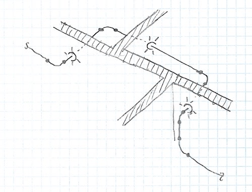
Your two important laser points are the "up" and "down" dots - the three side laser dots aren't needed and can even be taped off so nobody gets blinded down on floor level. Set the tripod up under a pipe spool, slide the laser level sideways until the upper dot hits the side of the pipe in the ocverhead. Then, directly on the floor, mark a small x on the concrete. Move the tripod sideways (across the pipe centerline as perpendicular as possible) and mark the point on the floor where the other side of the pipe OD wall is. On the floor, the mid-point of the two X's is the pipe centerline, the distance between the two is the pipe OD (insulation if present). Go down to the other end of the spool, and repeat. The line between the two CL points IS that pipe spool's centerline.

Keep repeating for major valves, tee, and reducers. Have your second worker/draftsman turn the "measurements" on the floor into paper drawings (CAD possibly, but that easier back in the office from the paper sketches.)

To get elevations (for pipe spools close to the floor), use a line-laser level (one that projects not dots from the self-leveling laser, but true lines.) then measure up or down from the starting point to get slopes, if you need slopes.

For elevations far up, use a digital laser distance tool (also hardware store quality), to measure from the floor up to the bottom of the pipe. Since you know the diameter of the pipes by marking (on the floor) between the two wall OD's, the height of the middle is 1R (1/2 OD) of the measured digital distance from the floor. BE CAREFUL! The floor is almost certain to slope itself for washing and drainage. So mark each site where you have "pipe elevation" written on the floor (concrete), and then use the level laser to determine the true height of the concrete at each elevation point.
 
If really complicated, can you do a point cloud using LiDAR?

Dik
 
You could definitely do a point cloud and there's software now that can semi-automatically convert the point cloud data + image to a 3D model.

But you'll probably still need someone from operations to help identify the piping if it's particularly spaghetti-like.

And hopefully you won't have stuff like this, which appears to be a standard for 100+ year-old pulp mills in Maine:

pipe_wall_pens_rpsy9v.jpg
 
Thanks everyone! We want to stick with low-tech methods and just get a general feel for the system. A 3D model would be great but is more than we require, and the point cloud and laser level systems are a bit overkill for our needs at the moment. I have some staff and some time available to throw man power at the project but limited resources to hire outside help and expensive gadgets, but I don't think I require a cadillac drawing here anyway.

Thanks LittleInch this is the thought process I was leaning towards, what I need would be more like a P&ID but with approximate lengths written on it, nothing fancy.

Gator, I have a couple of pipes that look like that....and some of my handsketches resemble that too! I have people here that know the pipes quite well and will help with checking the drawing over when it's on paper but the grunt work of pulling the information together will be done by people who are just getting familiar with the system still (including me, it will be a valuable lesson though).
 
Gator... once you have the point cloud, it's easy to attach labels.

Dik
 
One of my first assignments out of college was to order, and have installed, several thousand feet of Kynar lined, flanged pipe to replace corroded vent piping that ran though pipe racks. Isometric graph paper and a tape measure were all that was required. I was also a gymnast so climbing into the racks was not very difficult for me. this was in 1980. Plumb bobs can help with taking measurements.
 
I know you say you want to keep costs down but the cost of 3D laser scanning can is quite cheap and in my experience has less potential for errors or returns to site because some information was missed.

I would look at getting the systems scanned, based on the size I would expect you could have it done in 2 days including the site orientations etc.
 
Canadapipe said:
I know you say you want to keep costs down but the cost of 3D laser scanning can is quite cheap and in my experience has less potential for errors or returns to site because some information was missed.

Concur... we often use LiDAR for site work and mines (drones used). It is very cost effective. Biggest issue is getting the software to translate the point cloud into a drawing. Also use my laptop on site to try to catch anything that was missed. Sometimes stuff still gets missed.

Dik
 
Status
Not open for further replies.

Part and Inventory Search

Sponsor