Continue to Site

Eng-Tips is the largest engineering community on the Internet

Intelligent Work Forums for Engineering Professionals

  • Congratulations KootK on being selected by the Eng-Tips community for having the most helpful posts in the forums last week. Way to Go!

Tolerance for pipe to nozzle mating 1

Status
Not open for further replies.

kkoca

Civil/Environmental
Mar 6, 2023
4
Hello everyone,

I'm new here and appreciate your advice on the following issue:

What would be the mating tolerance between the suction/discharge pipe size and the pump's inlet nozzle? In my case, I'll pump water with a single-stage volute casing pump (Qmax = 72 m3/h). The inner diameter of the suction pipe would be 110.8 mm, followed by a reducer leading to a final inner diameter of 97.4 mm. At the pump size, the diameter of the suction nozzle is 100 mm. Would this be acceptable?

It's possible to slightly enlarge the end of the suction pipe from 97.4 to 100 mm, but I'm afraid that the flow uniformity reaching the impeller (nominal diameter = 155 mm) will also be affected. Could you please share your thoughts?

Many thanks in advance for your helpful feedback.
 
Replies continue below

Recommended for you

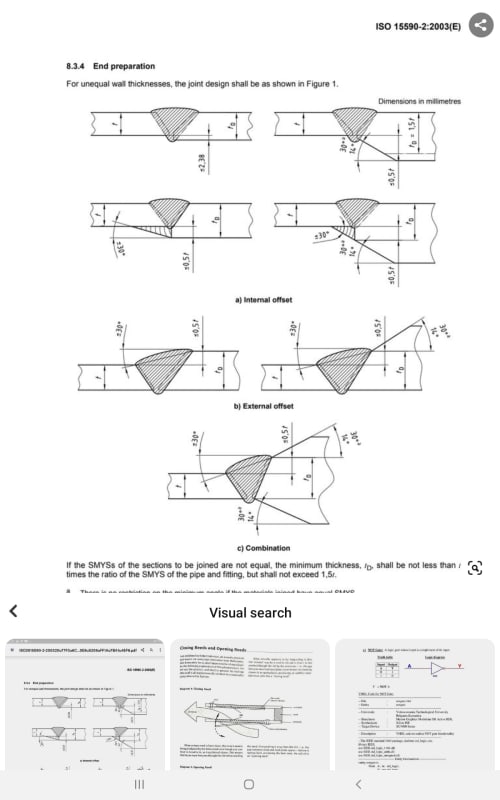
If the walls match up within this tolerance chart, you're good.
Weld_fit_pipe_fwnb9p.jpg


--Einstein gave the same test to students every year. When asked why he would do something like that, "Because the answers had changed."
 
But you're not welding all this are you?

There must be some flanges in this somewhere?

What are the OD and walk thickness here?

A sketch or similar schematic would be very useful. [pre][/pre]

Remember - More details = better answers
Also: If you get a response it's polite to respond to it.
 
Thank you for your responses - greatly appreciated!

Yes, I forgot to mention... There are some flanges in between. I don't currently have all details with me, but have tried to summarize in the following sketch and hope it helps:

SP_xgjdma.png
 
kkoca - wouldn't worry about such a small amount of diameter change - just ensure everything is concentric.,

It is a capital mistake to theorise before one has data. Insensibly one begins to twist facts to suit theories, instead of theories to suit facts. (Sherlock Holmes - A Scandal in Bohemia.)
 
Artisi - thank you for your response.

Would it then make sense to enlarge the pipe ending to 100 mm to ease alignment? Because I have the same problem (97.4 mm to 100 mm) just before the flow meter (DN100-ID).
 
Is the pump inlet and inlet/outlet on the flow meter exactly 100mm?

It is a capital mistake to theorise before one has data. Insensibly one begins to twist facts to suit theories, instead of theories to suit facts. (Sherlock Holmes - A Scandal in Bohemia.)
 
Is the OD the actual OD?

What material is this?

Remember - More details = better answers
Also: If you get a response it's polite to respond to it.
 
If you have flanges then the is no issue with alignment.

For the flow meter you normally need 5 to 10 D of pipe upstream of the same size and straight. [pre][/pre]

Remember - More details = better answers
Also: If you get a response it's polite to respond to it.
 
What it sounds like to me, is that you are asking about the acceptability of a "custom" reducer in your piping system.

What is your piping code ? .... Custom (i.e. non-ASME B16.9) reducers are permissable under B31.3

.... and have you checked min wall thickness for yor new proposed component ?

Have you asked the pump vendor for his commentary ??

MJCronin
Sr. Process Engineer
 
Hi everyone,

Many thanks for your useful comments and suggestions.

- Artisi, these values are based on the datasheets. I'll check the exact dimensions of the pump inlet/outlet and flow meter tomorrow after dismantling the old piping system.
- LittleInch, OD values are based on the datasheet. The material is polyethylene - PE100 pipe (SNR 17.6). Regarding the upstream distance, I've planned a distance of around 20 D, yet if the ID of the flow meter is exactly 100 mm, it is not possible to match the pipe diameter exactly. The ID of the pipe can either be 97.4 mm (SDR 17.6) or 101.6 mm (SDR 26).
- MJCronin, I'm not using a custom reducer. Here EN and DIN standards are used (Germany) - maybe this could be the reason. I've not yet discussed this with the pump vendor (ca. 20-year-old pump), but surely I can check with them.


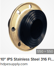
PE flanges are not always compatible with what I assume is a steel / cast iron pump casing?

And an exact 100mm ID is difficult to believe.

Remember - More details = better answers
Also: If you get a response it's polite to respond to it.
 
Consider your eccentric reducer carefully- installed the way you show, it may allow an air pocket to form in your suction pipe.
 
keyepitts

Correct the reducer should be rotated 180 degrees with the flat on top.

It is a capital mistake to theorise before one has data. Insensibly one begins to twist facts to suit theories, instead of theories to suit facts. (Sherlock Holmes - A Scandal in Bohemia.)
 
The PE flanges I have used are all similar to Vanstone flanges - Backing ring with a PE stub flange with seating dimensions similar to a raised flange face. We have found a need to be careful when ordering backing rings, some of the available materials have not performed well in our service.
Screenshot_from_2023-03-26_14-58-16_rbf7qr.png

Getting flange clamping force uniform is important for ensuring leak free service, so:
I have attached PPI TN-38: Bolt Torque for Polyethylene Flanged Joints.
 
Status
Not open for further replies.

Part and Inventory Search

Sponsor