Eng-Tips is the largest engineering community on the Internet

Intelligent Work Forums for Engineering Professionals

Tolerancing 'flush'

Status
Not open for further replies.

MattEdwards

Mechanical
Mar 19, 2024
12
0
0
GB
What's the best way to apply a 'flushness' tolerance to two nominally coincident surfaces? Is there a good way of doing so without needing to specify a datum?

2024-03-27_10h49_34_esso4f.png
 
Replies continue below

Recommended for you

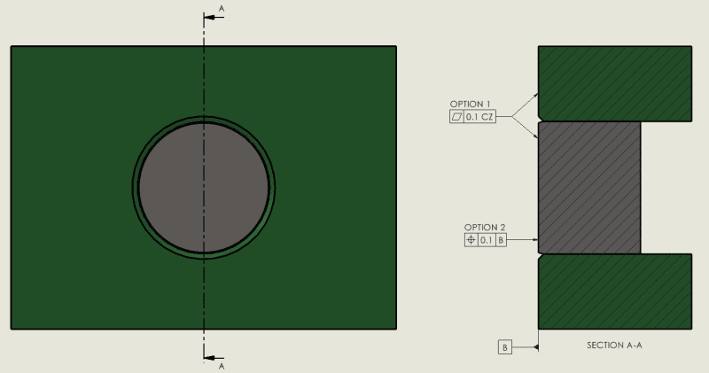
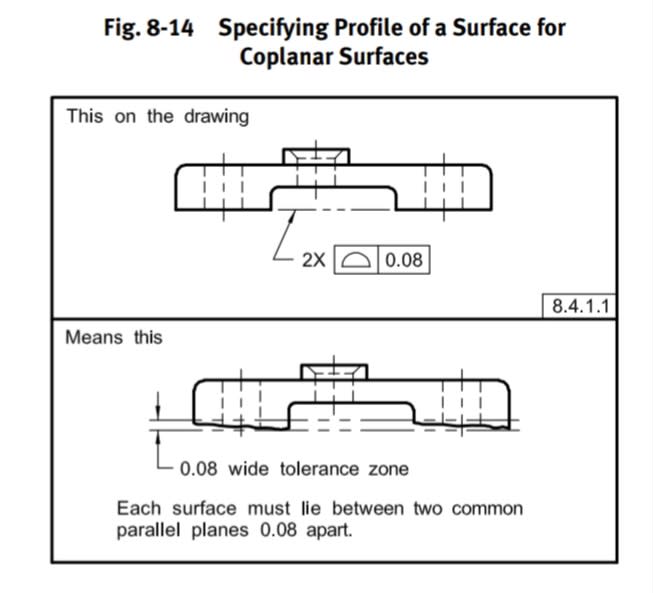
If I understand your intent right, I think flatness with CZ will suit it better. When making one of the surfaces a datum feature, the datum plane will be established based on the high points of that surface only, so you may be missing out some out-of-flushness, so to speak, that way. Also depends on the flatness requiremet or other tolerances that may be controlling the datum feature. Anyway, it's much less straightforward. I would also suggest considering profile of a surface with CZ. It would have the advantage of being somewhat more "global" specification. I recognize it's an ISO drawing, but in ASME profile of a surface is the preferred and better established control for coplanarity. That would also be applicable in ISO (although with a different grouping method—CZ and not just "2X"), so in terms of good communication with a varied audience, profile may be preferable.
 
Thanks Burunduk. Why is profile of a surface preferred?

I have used flatness with CZ before and found it causes some confusion even for the guys familiar with GD&T in our vendor's inspection department. Would it be acceptable to add 'FLUSH' somewhere around the FCF to help them out?

Is there a simple alternative that doesn't require a CMM and doesn't use GD&T to specify a tolerance on coplanarity? If the parts weren't nominally coplanar I'd just have a standard dimension between them, but the fact they are coplanar seems to make this impossible.
 
I'm a simple guy, I'd put a flatness tolerance on the whole thing and check it using a dial indicator mounted to a ground plate with the indicator probe reaching through a hole in the plate. Then I'd have some note or symbol to exclude the circular joint so the chamfer is excluded.

The value of that idea depends entirely on whether the inspection method suits your functional use. Maybe you need a CMM to scan the profile of both surfaces instead, but again I think a flatness tolerance will cover that well enough.
 
MattEdwards said:
 Why is profile of a surface preferred?  

Since flatness is a form control by definition while profile does control location among other things, it is preferred to use profile to control mutual location such as coplanarity between different surfaces. Sure, with the CZ modifier there is no substantial difference and there is a workaround called CF (Continuous Feature) in ASME too. However semantically, I would say profile is more correct.

Here is an example of coplanarity control from ASME Y14.5:
Screenshot_20240328_145315_Drive_srqgnl.jpg

Similar method is acceptable per ISO GPS, although with the addition of CZ.


MattEdwards said:
 Is there a simple alternative that doesn't require a CMM and doesn't use GD&T to specify a tolerance on coplanarity?  

CMM being required for profile inspection is a myth. You can use a height gage to inspect it like you would inspect flatness.
 
Profile of a surface is allowed and means the same thing as using flatness. I personally prefer to use flatness because it reduces ambiguity by explicitly defining the surfaces as nominally flat & coplanar.

Ryan.
 
Status
Not open for further replies.
Back
Top