Continue to Site

Eng-Tips is the largest engineering community on the Internet

Intelligent Work Forums for Engineering Professionals

  • Congratulations SSS148 on being selected by the Eng-Tips community for having the most helpful posts in the forums last week. Way to Go!

Torsion of I-Beams: Simplified Bi-moment Method 9

Status
Not open for further replies.

MegaStructures

Structural
Sep 26, 2019
376
Hello:

I am designing a small frame with significant torsion applied to some members in RISA3D. After going through the help manual I have found that RISA does not account for any torsion in beams, besides torsion caused by frame racking (fixed end condition, point torques at ends), similar to what is found in case 2 of AISC DG9. Of course this means I cannot trust the results from RISA and I need to input my own torsional stresses, so I have set out to figure out how to do the hand calc.

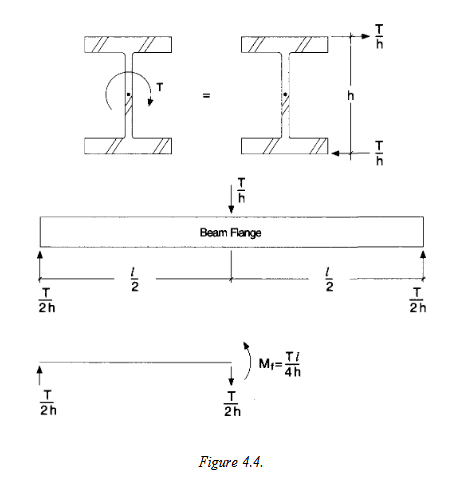
I reviewed some threads here on the forum and see some users suggesting the "equivalent tee" or "bi-moment" method to conservatively approximate the shear and normal stresses from torsional warping as suggested in AISC DG 4.1.4. The DG provides the figure below and says the normal stresses can be found by treating each flange as a beam and using the following equation σw= Mf/Sf where; Sf= (tf*(bf)2)/6. I assume the flange in the figure below (fig 4.4) is showing the side view of the entire length of the beam.

So, to me this method seems extremely simple and if accurate and conservative I am happy to have found it, because it will take me only minutes to check my beam. I do have a couple questions though and as I am typing this I realize this post might even be more suited for the RISA sub.

1) Is this method accurate enough (conservative is probably a better word) and at what unity ratio from pure torsion should I opt for a more accurate calculation of torsion stresses i.e. if torsion capacity calculated per this simplified method is 50% of the beams flexural capacity, but the beam still passes code checks should I be worried?
2) If this method is so simple and seemingly well suited for an automated calculation, why in the world does RISA not support it as a simple check? The fact that they don't makes me feel like I'm missing something about the usefulness of this method
3) In this review I have looked more at how RISA combines torsion stresses in the interaction equation and it combines torsional warping stress with weak axis moment, which seems to contradict what DG9 is suggesting, since the torsional warping moment found in the equation above is a stress normal to the flanges, or a major axis moment. How can this discrepancy be explained?

Torsion_DG9_v98oux.png
Axes_for_Torsion_Question_ulp4dv.png


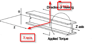
**As a bonus question has anyone used a shell element model to study the effects of torsion on I-beams that can speak on the efficacy of that method? I have created an FEA model of my frame with shell elements, the beams are relatively short < 10 ft W21x76's and support a point torque of 48 kip*ft and won't be limited by LTB and I'm not aware of any other buckling modes I need to be aware of (pure torsional buckling in the web?). I have ran a linear-static model and show very favorable stress results, which I am trying to confirm with this hand calc and of course the original RISA results.**
 
Replies continue below

Recommended for you

Mohanlal0488

I will definitely take you up on that! I'm away from my computer with my FEM on it today, but I will post it first thing tomorrow morning. You are correct in your understand of where the torsion is coming from.

canwesteng said:

Very helpful insight, I am glad I was considering all of the possible buckling modes already, definitely not something I want to miss.
 
I personally think if a program handled torsion in unique cases I would consider switching from RISA just for that functionality.

That's good to know. I should point out that I may have mis-represented the articles / references that I found on FEA modeling of I beam torsion. Those references related to how to do the ANALYSIS properly for all cases. At least that's my belief.... They don't address how to do code checks for them.

The problem with doing torsional code checks on WF beams is that the AISC code (in particular) doesn't do it properly. You have to go to an non-codified document (like the AISC design guide on torsion, or better yet, the British one) to come up with a reasonable code check procedure for this.
 
BTW, the British guide on torsion of WF is SCI P385: Design of Steel Beams in Torsion.
 
It is very possible to assess torsional effects on beams using FEA analysis, however I do not think this is possible using software like SAP2000, STAAD and most of the generally used structural engineering software(I may be wrong).

For STAAD that isn't correct. STAAD can do code check on beams with torsion. Last time I looked, it does it via AISC's Design Guide 9.
 
STAAD can do code check on beams with torsion.

WARose -

I think you'll find that the ANALYSIS in STAAD is incorrect. Torsional stiffness, deflections and rotations and such. Which means that when the beam is part of a larger structure, then the torsional moments the program calculates also incorrect.

It's possible that they have a post processor that evaluates the torsional moments on the beam and converts them into warping stresses and such. But, if those moments were incorrect to begin with, then how good is that code check?

Note: In addition to my previously mentioned biases, I'm not an expert on STAAD. Therefore, my comments is largely based on stuff I learned back in the 2000's on a much earlier version of STAAD. It's possible that they've done this since then. But, I tend to doubt it.
 
1) What is the situation at the top of your beam supported column such that it is inducing this torsion? Frankly, unless the supported is flag poled, I'm skeptical that this is actually a situation in which most engineers would consider the column base fixed and the torsion in the beam necessary.

2) If your sketch proportions are anywhere near accurate, I would argue that this is not a member experiencing torsion but, rather, a connection experiencing torsion. Better to get the situation straight before investing the time to execute member checks that don't lead to meaningful answers.

In short, can you tell us a bit more about the structure surrounding this joint?

 
Josh - nothing has really changed. While you're right that STAAD may underestimate the torsional moment, it is being accounted for somewhere else in the structure, likely as strong axis moment, so a load path is being provided anyway. This is basically how I would do a hand calc anyway. My concern is if it properly accounts for torsional "free","pinned","fixed" support conditions per DG 9 (absolutely atrocious nomenclature by AISC imo, but that's another discussion). In general torsion in steel structures should be something like OP situations where it's statically determinate - if it's statically indeterminate you should be able to find a way to design it out (just my opinion again).
 
WARose -

I think you'll find that the ANALYSIS in STAAD is incorrect. Torsional stiffness, deflections and rotations and such. Which means that when the beam is part of a larger structure, then the torsional moments the program calculates also incorrect.

The question was if STAAD can do it at all. And it can. It's certainly not 100% accurate.....but then again neither is RISA or any other FEA package I have used.

I have found STAAD to overestimate stresses.......but STAAD should be complementary to things like the afore mentioned spreadsheets and other resources.

 
Canwesteng -

Those are really good points. I think the reason why so few engineers are interested in "increased accuracy" as far as torsional warping analysis and design goes is because they don't believe it is an issue in reality. That it's one of those things where if it starts to become a problem, the structure softens up and deflects, then the load re-distributes.

Kind of like in ACI when we talk about compatibility torsion vs equilibrium torsion. And, if you're designing a structure where you rely on a WF beam to resist equilibrium torsion, then you're probably doing something wrong. If not, then it's compatibility torsion and probably isn't as much of an issue as you think it is.
 
@MegaStructures

Looking forward to seeing the model.

@WARose

I was talking about about torsion purely from an analysis perspective. Using codes of practice allow design through simplified analysis methods, ie linear static. An equivalent design can be performed based purely on analysis, however there are aspects that may be very difficult to model or assess such as imperfections in material. In general almost all the structural checks provided in codes of practice can be done through FEA.


KootK said:
If your sketch proportions are anywhere near accurate, I would argue that this is not a member experiencing torsion but, rather, a connection experiencing torsion. Better to get the situation straight before investing the time to execute member checks that don't lead to meaningful answers.

Admittedly the drawing is not actually drawn to scale, but it shows more or less the correct configuration. The base plate is welded at its edges, which are ~1" from being directly above the beam web. The column is supported top and bottom and does transfer some moment to the base plate, but mostly I am worried about the vertical force coming from the column, which is quite big ~200 kip.

I am picturing that the vertical force from the column would transfer to the base plate, then base plate will bear on beam flanges and tend to twist the supporting beams inward like the image below. Thoughts?


2020-08-21_17_04_42-Scan_Aug_21_2020.pdf_-_Adobe_Acrobat_Reader_DC_ge8g6l.png
 
Yeah, stiffen that damn base plate, from the top or the bottom, until torsion is a non-issue. Torsion's fun to talk about but generally impractical to deal with in large quantities and a veritable money pit of disappearing consultancy fees.

C01_ogsd4b.jpg
 
I was talking about about torsion purely from an analysis perspective. Using codes of practice allow design through simplified analysis methods, ie linear static. An equivalent design can be performed based purely on analysis, however there are aspects that may be very difficult to model or assess such as imperfections in material. In general almost all the structural checks provided in codes of practice can be done through FEA.

I'm not sure how you could do a torsion design "purely from an analysis perspective". (At least without it being ridiculously cumbersome.)

 
Your sketch shows a "compatibility torsion" rather than "equilibrium torsion", which occurs when there is only one beam to support the off axis column. Since the torsions rotate toward each other, the effect of torsion is minimized, if the beam flange and the gusset-baseplate assembly are made rigid as mentioned by KootK.
 
A pair of stiffeners would safe you a lot of trouble.

image_wo5fik.png
 
KootK said:
Yeah, stiffen that damn base plate, from the top or the bottom, until torsion is a non-issue.

I like it. I didn’t share that there are architectural features that don’t let me add stiffeners to the base plate. Of course the 3” base plate itself is fairly stiff, so I may be exaggerating the torsion concern anyways. I do wish there was an easy way to prove my 3” base plate was stiff enough to not add significant torsion to the beams, but I’m not coming up with an easy method outside of an FEA study and think it would just need to be an “overkill” solution like the big vertical stiffeners.

How do you feel about stiffeners added to the beams, similar to what retired13 shows?
 
The stiffener will prevent the excessive bending of the flange, and transfer load to the web if it is stiff enough (by design). You need to make sure the web has adequate strength to prevent it from buckling too.
 
MS said:
How do you feel about stiffeners added to the beams, similar to what retired13 shows?

I don't support that as it will tend to increase the torsion on the beams rather than dissipate it. The reaction points for the base plate will move further from the beam webs.

OP said:
I do wish there was an easy way to prove my 3” base plate was stiff enough to not add significant torsion to the beams

Try this:

1) Assume that the support reactions for the base plate are centered at the supporting beam webs.

2) Treat the base plate as a simple beam and calculate the deflection at the interior tips of the beam flanges.

3) Use #2 to estimate a max supporting beam rotation at the support point, assuming the cross section to be rigid, and give some thought to if that is a comfortable number when treated as an imposed rotation.

4) Use #2 to estimate a max imposed beam flange rotation at the web and see how that compares to the flexural yield stress of the flange to see if that's a comfortable number.
 
My version of stiffening from the bottom would look more like this. Whether or not it would be feasible depends on which elements of this setup are new and which are existing. While we're at it, care to shed a little light on that?

C01_ciqlzl.jpg
 
I like the invert tee idea, but I won't give up the stiffeners. It can be modified by connecting a pair of channels/angles, or a single coped beam acting like strut in between.
 
Status
Not open for further replies.

Part and Inventory Search

Sponsor