Eng-Tips is the largest engineering community on the Internet

Intelligent Work Forums for Engineering Professionals

Torsion on shaft with square end 3

Status
Not open for further replies.

SR71-110

Mechanical
Feb 1, 2023
12
0
0
US
Hi All,
I have a shaft attached with this thread. I have couple questions:
1) What would be the best way to control the central axis of the shaft given I have a square end on one side.
2) How to calculate torsion for such a shaft?
3) It's a power transmitting shaft, what would be a good setup for FEA? to apply radial loads?

number Labels on diagram description:
1) Square end with chamfered edges.
2) circular diameters
3) groove
4) fixed pin

Thank you
 
 https://files.engineering.com/getfile.aspx?folder=5e55b07f-d02a-4d96-b2f7-6a0d1c412032&file=Rough_sketch.PNG
Replies continue below

Recommended for you

Hi SR71- 110

Is the shaft made from one piece? FrOM the sketch it a looks like the shaft is welded together and should this be the case then the most critical parts will be the welds

“Do not worry about your problems with mathematics, I assure you mine are far greater.” Albert Einstein
 
Hi SR71-110

Well when I have stressed shafts in torsion with a square end section, I have assumed the square section to be circular with a diameter equal to the distance any two of the parallel sides.The torsional stress can be worked out for each section individually. Moving on to the deflection you can calculate the angular deflection for section and then sum them together also.

“Do not worry about your problems with mathematics, I assure you mine are far greater.” Albert Einstein
 
To add to desertfox's comment. The formula for max torsional shear stress in a square section is Tau = (0.601*T)/a^3, where "a" is half the distance across the flats. Whereas in a circle it is Tau=(2*T)/(pi*r^3). The circle assumption leads you to overestimate the torsional shear stress by roughly 6%.

An assumption which I think is valid to make in most cases, however it's nice to know how conservative it is if someone questions it.

Formulas from Roark's Formulas for Stress and Strain
 
Does The groove at 3 really leave material only 1/8 as thick as the square at 1 ?
Is the result a small diameter or a thin blade.
 
So the square drive is connected to the rest of the shaft with an integral, very small diameter, quill shaft?

I'd say there is your torque limiting feature right there.
Are you looking to solve for the torque that will bust the small quill ?

And there better be NO radial loads applied to the square.
 
There is a groove between the square and the shaft as a means for transition to smaller diameter. You are correct, this groove will be my high stress area. You are correct, I am after the failure of the system because of the groove. Do I just need to do Torsion calculation? how can I do that? Sorry I am new to this :(.


I
 
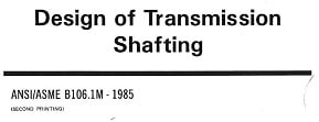
Find the following ASME standard -
b106_sd9ms2.jpg


This standard indicates the effects of stress concentrations and also the nature of torsional and bending moments. The shaft equation presented assumes that bending moments are alternating, and torsional moments are constant, and bases the calculated shaft diameter on yield strength for the torsional aspect and fatigue strength for the alternating bending moment. Refer to figure 5 in the standard to find stress concentration factors for your configuration.

You are climbing out of a pretty deep hole if your employer is not providing a mentor who can help you learn these things. Do not be embarrassed to admit what you know and don't know, it saves time, money, and your sanity.
 
Status
Not open for further replies.
Back
Top