Continue to Site

Eng-Tips is the largest engineering community on the Internet

Intelligent Work Forums for Engineering Professionals

  • Congratulations KootK on being selected by the Eng-Tips community for having the most helpful posts in the forums last week. Way to Go!

Torsional Stiffness Check for Extended Shear Tabs 1

Status
Not open for further replies.

anewbieengineer

Structural
Apr 3, 2012
10
extended_shear_tabs_esmbgy.png


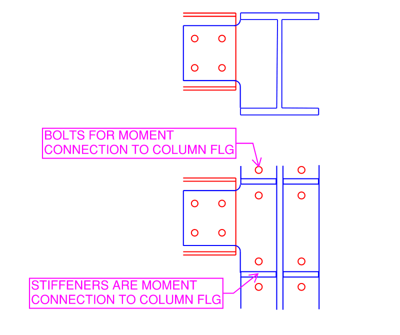
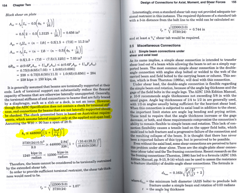
Hi All, I am practicing in Canada but very often we refer to AISC manual for information not available in CISC. I am trying to work on an extended shear tab tool (please refer to attached picture above) and am trying to make it to cover as many different scenarios as possible. I like to use shear tabs whenever possible because it is both economical for fabrication and erection. However, design method provided by AISC is only applicable for beams that are laterally supported, which is common for building with slab and deck, but for heavy industrial projects, infill beams and stringers are often not laterally supported. I was doing a bit of research and came across an example in the text book, "Handbook of Structural Steel Connection Design and Details," Sec Ed. by Akbar R. Tamboli. Under section 2.4.6, he presented a check based on the Australian code for torsional stiffness of extended shear tab (please see second picture attached).
Tamboli_145-155_chg1gl.png

However, he did not provide a clear reference to the origin of the equation. My company is not interested in purchasing an Australia code and I was not able to find further info online. Anyone can shine some light on me. Thanks!!!
 
Replies continue below

Recommended for you

That (specific) equation doesn't ring a bell.....but most of the basis for torsional bracing in AISC code (in fact, for just about all bracing) traces back to the various papers of Joseph A. Yura. (In their commentary, AISC also references Taylor & Ojalvo's paper 'Torsional Restraint of Lateral Buckling', ASCE, 1966.)

If you have a AISC manual, they make clear the bracing requirements (see Appendix 6 in the 13th ed. for example). I've used it to verify a support is adequate for lateral and torsional restraint.
 
Thanks for your reply WARose, but in this case, I am not trying to brace the support beam but to size the shear tab to be torsionally stiff enough so that lateral bracing is not required. "That (specific) equation doesn't ring a bell"... Yeah the equation is from Australia, according to the author.
 
I can't comment on the Australian equation but can offer insight into how I remember checking extended shear tabs as per CISC with some AISC guidance. We would determine a minimum plate thickness to ensure LTB doesn't occur prior to the plate reaching its plastic strength. This used the Elastic LTB Equation and assumed no warping contribution.
 
This may not get you all the way, but I checked through and there are some good references (Yura, Johnson, etc.) that have more detailed papers out there on the subject.

Link
 
Done the same as skeletoron, but using the formulas for buckling from the Muir paper on extended shear tabs. It used to be available for free on his website, but may be behind an AISC paywall now.
 
Conceptually the design should be simple - check the rotation of the beam under maximum torsion allowed, and design the shear tab stiff enough to close the gap (rotation angle), on top of shear and flexural stresses. Then check the beam web and bolts...writing up to here, I think it is rather much easier just to brace the beam and prevent this phenomenon to occur.
 
Not always. I understand what he means by industrial settings. Long span bays, discreet rather than continuous braces, required clear space for equipment/crane movement. Putting in what essentially amounts to a web of braces to prevent torsion is at best costly and and worst impedes operations in the facility. Determining how thick a plate needs to be to solve the problem may be more work for the engineer, but this is an environment where the clients are more likely to understand the value of that effort and pay for it.
 
....but in this case, I am not trying to brace the support beam but to size the shear tab to be torsionally stiff enough so that lateral bracing is not required.

That's sort of contradictory. Not required for what then? The tab itself? The beam that the tab is framing into?

 
Beam supports need to resist beam rotation. I would assume he doesn't want to brace the tab itself, but you could also brace the beam at the point of support.
 
Thanks for everyone's reply and discussions.

WARose said:
That's sort of contradictory. Not required for what then? The tab itself? The beam that the tab is framing into?

As phamENG has further elaborated the situation in my question (Thanks phamENG), I actually do not want to introduce any bracing to the beam or at the connection. I think I should explain a little more precisely. In Canada, fabricator's engineers design the connections. So when the structural consultant design the beams, I believe they would have assumed that the beam is supported by a connection that is torsionally stiff enough. AISC design procedure assume that the end of the beam is braced as stated in Larry Muir's article, A Shear Connection Extends Its Reach.

"If the end of the beam is not braced, is the design procedure in Part 10 still applicable?

No. The design procedure assumes that the end of the beam is braced. The beam can be braced by an actual brace or by the slab, deck or other suitable means. The cope checks in Part 9 of the Manual also assume that the cope is braced at both ends of the cope. This has always been the case and has been clarified in the 15th Edition Manual. Since the design procedure for the extended single-plate shear connection references the cope checks, it must satisfy the same assumptions. Also, as stated previously, if the flexural strength of the beam is to be determined using Chapter F of the Specification, then there must be adequate torsional restraint at the supports. If the beam is not braced at its end, then the strength and stiffness of the plate must be evaluated. If there is insufficient strength and/or stiffness, then this must be accounted for in the design of the beam. Neither the Specification nor the Manual address this problem.

If my beam is not sufficiently braced at the end, should I opt for a torsionally stiff connection configuration?

Yes, but there may also be other considerations. Bracing is not mentioned in the Manual for any of the other shear connections discussed in Part 10. It has long been established practice to provide a connection that is at least half the depth of the beam and implicitly assume that there is sufficient torsional restraint. However, the presence of a cope could invalidate this assumption. Also, as stated previously, the cope checks in Part 9 assume a brace point at the end of the cope. Even the strongest and stiffest connection will not provide sufficient restraint if it attaches to a coped section that does not possess sufficient strength and stiffness."

Since shear tab is economical and for some situations, like the second sketch in my 1st post, extended shear tab is almost the only option available to easily connect the beam to the column's web, therefore, I would like to establish a check for torsional stiffness of the shear tab to meet the requirement that there is adequate torsional restraint at the support instead of bracing the beam ends. Hopes this further clarifies the situation.


That requirement is not from the Australian steel code. It may be from some research paper or similar. Maybe its in the references in that book but not specifically referenced?
 
"If the end of the beam is not braced, is the design procedure in Part 10 still applicable?

No. The design procedure assumes that the end of the beam is braced. The beam can be braced by an actual brace or by the slab, deck or other suitable means. The cope checks in Part 9 of the Manual also assume that the cope is braced at both ends of the cope. This has always been the case and has been clarified in the 15th Edition Manual. Since the design procedure for the extended single-plate shear connection references the cope checks, it must satisfy the same assumptions. Also, as stated previously, if the flexural strength of the beam is to be determined using Chapter F of the Specification, then there must be adequate torsional restraint at the supports. If the beam is not braced at its end, then the strength and stiffness of the plate must be evaluated. If there is insufficient strength and/or stiffness, then this must be accounted for in the design of the beam. Neither the Specification nor the Manual address this problem.

Ok.....but Appendix 6 [13th ed.] is still applicable here. As far as I know, those lateral/torsional stiffness requirements can be used not only to determine adequate restraint along a beam.....but also to determine adequate support conditions for the code lateral torsional buckling allowables to be applicable.

So while I don't know the source of the equation in your original post.....you have options available to you in AISC. (And their source is cited in that text.)
 
I asked the same question to the AISC steel solution center a few years ago, here is the answer I got from Larry Muir:

"First I have to state that the AISC Manual requires this because the AISC Specification requires it. Section F1.(2) states, “The provisions in this chapter are based on the assumption that points of support for beams and girders are restrained against rotation about their longitudinal axis.” You concern is a valid one, but unfortunately there is not a lot of published guidance. The Australian Steel Institute (then called the Australian Institute of Steel Construction) 3rd Edition of “Structural Connections” presented a discussion that led me to the conclusion that an end connection whose torsional stiffness was greater than 20 times the torsional stiffness of the beam would reduce the flexural strength of the beam (as calculated using Specification Chapter F) by about 10%, an acceptable reduction. For a tab plate or a double cope the torsional stiffness can be calculated as GJ/c. Where J = 0.33dt^3 – for the tab plate or coped section and c= the distance from the face of the support to the end of the beam or end of the cope."

Also, I recommend you to check the Bo Dowswell's paper "TORSION OF RECTANGULAR CONNECTION ELEMENTS" published in the AISC Engineering Journal.

Hope this help!
 
There may be some insight with the UofA's research group. There are some recent reports here and you can also track down their full list of SER here.
 
Status
Not open for further replies.

Part and Inventory Search

Sponsor