Continue to Site

Eng-Tips is the largest engineering community on the Internet

Intelligent Work Forums for Engineering Professionals

  • Congratulations KootK on being selected by the Eng-Tips community for having the most helpful posts in the forums last week. Way to Go!

Torx head profile of a surface questions 3

Status
Not open for further replies.

sendithard

Industrial
Aug 26, 2021
166
I'm trying to establish if there is a need to establish a datum C for a torx head screw, and how it could be done properly with GDT. My only understanding til this point of leaving out locking down rotation is on purely cylindrical revolved geometry.

I just encountered a torx print that did not have datum C and allow rotational freedom in Z. Maybe this is correct, maybe it is dealers choice, and that is why I'm asking.

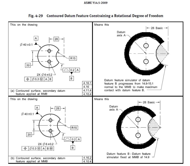
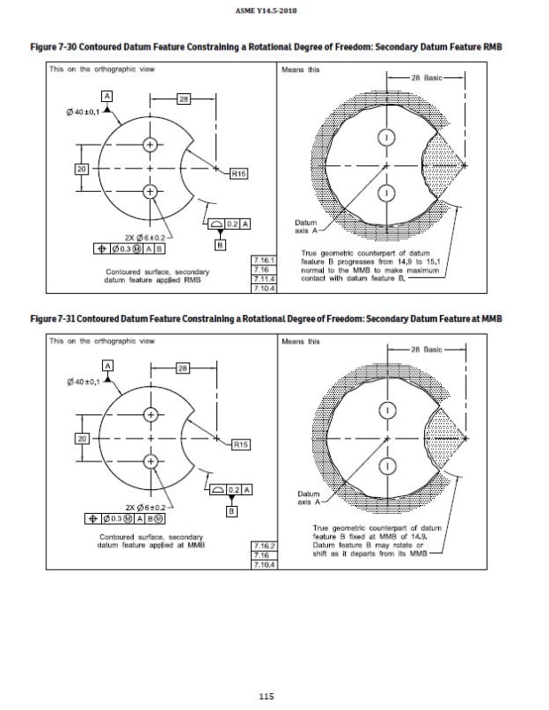
In my attempt to lock down rotation, I attempted to use a radius surface for the datum feature, but when I looked up the standard it shows the radius as a basic dimension then the datum is attached the profile of a surface FCF....both 2009, 2018 standard pics are below....they are in different chapters so I put them below.

If I followed suit into the standard and created datum C from the profile of a surface callout it would conflict with the desired profile callout listed on my print. On the otherhand if datum C is listed as is on my print and I measured this with a CMM and a cad model the profile of a surface could get all messed up depending on the radius.

If I just forgot about datum C and hence rotation and made the radius basic, the problem seems to go away.

I'm confused. Thank for having a look. 2009 Fig. 4-29 & 2018 Fig. 7-30

*edit...the prints I've come across so far with torx like heads use min max diameter as basic dims for the drive head, so I followed suit here.
*edit...the datum surface is not much in terms of degrees....I know that is a problem for cmms,but is there something written about this for the standards?
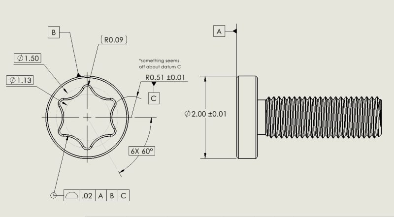
datum_c_issuee_nuv6rb.jpg

radius_datum_2009_czitb7.jpg

radius_datum_2018_dsiefu.jpg
 
Replies continue below

Recommended for you

Unless something other than the recess requires it "C" serves no function.

Also, all dimensions describing a surface controlled by profile need to either be basic or, in the special case of a single nominally flat surface, not exist.
 
It would only make sense to lock the rotation of the Torx about the axis if it had to be at some specific orientation relative to something else. Then that something else would become the tertiary datum reference. Not useful for a simple screw. As it was pointed out, all radii defining the true profile of the Torx shall be basic if it is to be controlled by profile. BTW, if it is a standard Torx, there is ISO 10664 that can guide you on the dimensions and allowed variations.
 
Thanks for the replies, I figured something was wrong with the toleranced surface, but I overlooked the referenced radius as well. I saw a print with profile that included the small lobe referenced so that was incorrectly put together. Appreciate the ISO reference as well, I'll look that up.
 
Are you actually having screws made to spec from custom tooling? Seems like an awful waste of effort for something so standardized. Almost certainly better to spec compliance with an existing standard, e.g. SAE AS8538.
 
I saw two prints recently from customers with a profile of a surface callout, both if I remember with a reference dim on a lobe. I'd tend to agree with what you said, I do prints anytime I can yo learn both the mechanics of using diff cad drawing tools and improving my gdt. I'm also doing a practice part on a cmm to align this more effectively.
 
Looks like a pretty large Torx.
The largest standard one is T100, and on it the diameter specified as 1.50 in your drawing is .871.
 
Yeah - a 2 inch diameter screw head. How likely is that?

"(a) A zero is not used before the decimal point for values less than 1 in."

If it's per Y14.5, then this is a metric dimensioned drawing of the recess to accept s T5 tool.
 
If it's metric a leading zero is missing for the profile tolerance.
 
Oh, no, a drawing that isn't compliant. Glad you are there to point out the tiny flaws when ignoring the clues to the actual size and making big errors.
 
And...
2.0+-0.1 should be 2+-0.1. 1.50 basic should be 1.5.
 
I always figured that these rules about leading and trailing zeros were intended solely so nitpickers could have something to complain about when they didn't understand the engineering intent of the drawing. That way they could feel they were making a contribution and not feel left out. If either approach was clearly better it should be the only approach.

Interesting that it's important to nitpick now when it didn't occur as a problem earlier.
 
3D,
You are obviously confused because you are the one who brought up the "zero is not used" rule.
I pointed out the clues to an inch drawing.
 
I didn't nitpick the drawing. You did. Still, it's good to have rules to allow easy confusion to happen rather than not caring about leading zeros trailing zeros and instead looking at the title block to see what the units are.

Maybe they are scaling a metric recess by 25.4 times when a more typical and less costly choice would be a spline.

Keeping track of zeros sure gives checkers something to do when they don't have any other useful thing to add.
 
That's my bad on including the leading zeros, sorry about that, I do like that rule. This is a personal drawing for an oversized 3d printed torx head I'm using to probe on the cmm and pick up the larger torx radius to orient the part with leeway as to user error upon placement orientation in a collet and without the operator having to manual find surfaces. The size of the print is to make the 2mm probe tip have similar room that a .5mm tip would inside something like a size 10 torx. I can barely see a .5mm tip let alone the shaft so I'm using a larger probe to practice on.
 
3D, I didn't nitpick on the drawing. As usual, you fail to see the context, just like you failed when you were nitpicking on the plural verbiage of the standard in the simultaneous requirement definition.

Edit: by the way,
3D said:
Yeah - a 2 inch diameter screw head. How likely is that?

Not less likely than an approximately M1 sized thread with a T5 Torx.
 
sendithard, it's all good. I figured it's an inch drawing because there are more clues to it than to a metric drawing, that's why I was intrigued by the size of the Torx. Thanks for the clarification.
 
3D said:
I always figured that these rules about leading and trailing zeros were intended solely so nitpickers could have something to complain about when they didn't understand the engineering intent of the drawing. That way they could feel they were making a contribution and not feel left out. If either approach was clearly better it should be the only approach.

"something to complain about..."

"didn't understand the engineering intent of the drawing..."

"could feel they were making a contribution and not feel left out"

3D, that turned out to be a precise description of most of your input in this thread.
 
sendithard,

If the goal was to also encompass the radius specified C as part of the all-around profile tolerance, in addition to the fact that it needs to be basic the result is that you have created a self-referencing specification. This means that the datum feature C is controlled by a profile tolerance which also references C in |A|B|C|. Now since C only constrains [w] rotation I don't believe you'll get the normal effects of a self referencing tolerance zone as when translational DOF are being constrained (ie: half the tolerance zone is available) however there may be some unintended consequences - at the very least you've created a potential headache for the people inspecting it unless this is something they are familiar with.

In this case as others have noted you could just remove C as it really adds nothing as you probably don't care about orientation of the torx feature to any other feature on this bolt (note - all DOF do not always have to be fully constrained in every case, as in this case [w] rotation can be left free as orientation/clocking of the torx to the thread doesn't matter), however its important to be mindful of this self referencing as its easy to specify a datum feature and then wrap it in an all-around/all-over profile tolerance that specifies the same datum feature. There are situations where its potentially desirable however in my opinion it should be generally avoided unless necessary.
 
Status
Not open for further replies.

Part and Inventory Search

Sponsor