Continue to Site

Eng-Tips is the largest engineering community on the Internet

Intelligent Work Forums for Engineering Professionals

  • Congratulations KootK on being selected by the Eng-Tips community for having the most helpful posts in the forums last week. Way to Go!

Total Runout Greater Than Size Tolerance 2

Status
Not open for further replies.

donatim24

Mechanical
Jun 13, 2018
27
Hello,
I'm encountering an issue on one of my drawings similar to that shown in the picture below (see also this link:
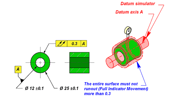
Total_Runout_Example_pwbzpn.png


The size tolerance on the shaft is smaller than the runout tolerance on the shaft. The link above mentions that in such a situation, total runout controls location and orientation. In that situation, is there any practical difference between total runout and position RFS? If it helps, my specific application is setting two coaxial bearing seats as datums A and B and controlling those datums with total runout referencing A-B.
 
Replies continue below

Recommended for you

OP said:
In that situation, is there any practical difference between total runout and position RFS

Assuming ASME:
Yes, it is a difference.
runout will control the surface
position will control the axis
 
Yes, sorry that I left out the detail that I am asking in reference to ASME Y14.5 2009. I agree that position is an axial control. Since form is not controlled by the runout, how does the distinction between axial control and surface control impact measurement and performance as they relate to locating coaxial bearings on a shaft? I thought I read in the linked article that runout controls surface (presumably when it controls form) and the axis.
 
Also maybe fig 12-6/ ASME Y14.5-2018 could be used to clarify the concepts and the relationship between runout and position.
 
donatim24,
Imagine that the actual outer diameter from the Tec-Ease example has been produced as an oval having local size equal to 25.1 between 12 and 6 o'clock and local size equal to 24.9 between 3 and 9 o'clock.

With the total runout tolerance in place, the center of the oval will be allowed to be only 0.1 (0.2/2) off of the datum axis A. That's because form error of the nominal cylinder has already consumed 0.1 [(25.1-24.9)/2] of the total allowable total runout error of 0.3.

However, with a position tolerance of the same value in place, the oval will be allowed to be 0.15 (0.3/2) off of the datum axis. That's because position tolerance, by its definition, does not "see" any form error of the actual feature.
 
Thank you both for the explanation. The article that greenimi linked led to me trying to formulate the point that pmarc articulated better than I could, that runout controls form and position together in a way that deviations in form take away allowable position deviation, while for a position tolerance RFS, the allowable position deviation stays constant. Thanks for the help!
 
Status
Not open for further replies.

Part and Inventory Search

Sponsor