Eng-Tips is the largest engineering community on the Internet

Intelligent Work Forums for Engineering Professionals

Touring car rear suspension

Status
Not open for further replies.

Madssc

Automotive
Nov 15, 2009
2
0
0
DK
Hi Guys,

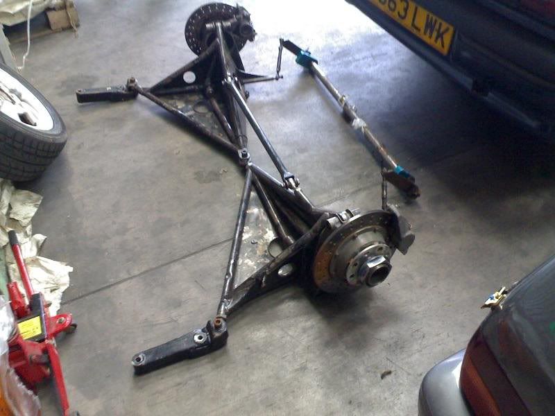
I am having a bit of hard time getting my self arround this type of rear suspension.

I can see that roll center location must be defined by the link on top og the triangles and then the angle of these like if it was a lower wishbone, but i find it hard to see which pickup points to combine in order to visualize it.

Does this kind of suspension has a name, I know it was used on older touring cars and the same is used on newer race cars as well, but i really need someone to explain it to me.

Thank you very much!

R19touringCarRearSuspension.jpg
 
Replies continue below

Recommended for you

I've no idea what to call that suspension but it seems to me it exists to:

[ul][li]fit onto the chassis pickup points of a twist-beam rear axle[/li]
[li]be stiff (low compliance effects)[/li]
[li]be adjustable in camber[/li]
[li]be adjustable in toe[/li][/ul]

Regards, Ian
 
Thanks for the reply Ian had hoped that some of the "heavy weights" [that is meant as a compliment] like Brian Peterson Greg Alcock and many others might have chimed in with comment. Which leads me to my next question has anyone got a lead/link to some advanced stuff on front wheel drive designs etc. Tmoose seems to have an huge archive on things tech.
Golfpin
 
Sorry about the typo Greg... but more to the point Mdssc says that this layout was used by some one? Who? am very intrigued see a lot of good points [like to be positive] any negs out there.
Golfpin
 
On the assumption (always dangerous) that the centre hardpoint goes to the body then the thing is fundamentally a semi trailing arm. The addition of the link between the 2 arms high up then seems to me to lock up the mechanism in a very strange way I think the net effect will be that it is very stiff in bounce ie lots of fake anti dive anti squat, but will still allow some roll motion with a very defined ratio of inboard to outboard vertical wheel motion.

Cheers

Greg Locock


New here? Try reading these, they might help FAQ731-376
 
Thanks to all, yes that crosslink has me confused out with the cardboard pieces and drawing board see if I can make any sense of it....
Golfpin
 
Descriptions of the Williams racing Renault BTCC Laguna generally seem to say trailing arm with torsion bar rears suspension .

A modern driver (Andrew Jordan) had this to say about driving one today.
“The Laguna felt much more on a knife edge,” he added. “It was very different to drive, it feels like it darts around, certainly a lot more on cold tyres. I felt like I was on my back foot with it, because it’s hard work even to stay on the straight. I’m sure as you get more used to it and the tyres come up to temperature it gets better, just it was a bit of a shock going from the Vauxhall to that and how different it actually felt.”
-
The suspension shown in your first post sure looks battered and bent. And more like a prototype or even a home made spare than any of the pictures in the later posts (which have coilovers).
 
Sincere thanks Tmoose, the original/opening pics are from Madssc I am just an old[very in mod, terms as far as suspension geometry/technology is concerned] a former f1 techie just fascinated by the new stuff! suffice to say that I am more confused than ever but.. as enthusiastic as can be expected at.............71.3 years I think that is.
Golfpin
 
Just thinking about this, as I said making assumptions is dangerous. If the two arms are joined to each other, but not the body, at the centreline , with a ball joint, then you do allow articulation in bump, and as somebody said, it behaves more like a twist beam. The major issue with it seems to be that you would get a jacking effect if there was opposing lateral forces at the contact patches, but that is not a very important load case. You could even mount a coil spring at the centre, this would provide no anti roll springing.

You could use a bush instead of a ball joint, that would reduce the jacking effect.

Cheers

Greg Locock


New here? Try reading these, they might help FAQ731-376
 
I don't think the centre hard-point is meant to attach to the body.

If my hunch is correct then this replaces a twist-beam, so the hard-points are only the front mounts of each fabrication, and the top mounts of the springs / dampers. The ARB may be something the original car did not have?

The camber looks to be adjustable by that link across the top, the toe adjustment is hidden. Rear toe & rear camber settings will be very powerful for dialling in the tyre temp lateral distribution (camber) & braking / turn-in stability (toe). That's why the designer has effectively bolted an upright to a fabricated beam, via sphericals and (probably) shims - to maintain or even increase installation stiffness while allowing fine adjustment.

Regardless of the details of this particular suspension, if I were designing a FWD touring car rear suspension my key criteria would be installed toe stiffness, followed by installed camber stiffness, followed by easy adjustment of toe & camber, followed by easy adjustment of roll stiffness.

Regards, Ian


Toe could also be adjusted - although not independently of the camber - if that center joint is a threaded ball joint, which it looks like it is.

I hadn't replied earlier (despite being called upon) because I've never seen something like this before and couldn't see how it worked, but I can see it now, as an adjustable substitute for a twist-beam axle, in which "da rulez" call for using only the attachment points to the chassis that the original production car used.
 
I think the later Corvair "rear toe adjusters"
were actually intended to provide controlled
roll steer.

They were serendipitously handy
for adjusting rear toe.

... Which more than half
the time had to be done twice because the
gorilla in the pit forgot that the car
was facing backwards while he was
adjusting rear toe.

I have the t-shirt.


Mike Halloran
Pembroke Pines, FL, USA
 
WONDER HOW MANY OF THOSE GORILLA,S IN THE PITS NEW THAT THE TOE IN ON THE REAR OF THE BEE SWING AXLE BEETLE WAS ADJUSTABLE AND THAT ON REMOVING THE TRANSAXLE IT SHOULD HAVE BEEN PREMARKED AND CHECKED AND SET AFTER ASSEMBLY. A LOT OF THE POOR HANDLING ASCRIBED TO THESE GREAT LITTLE CARS WAS AS THE RESULT OF NO REAR TOE, OR BETTER ZERO TOE ONE SIDE AND TOE OUT ON THE OTHER
OLD TIMER GOLFPIN
 
FWIW the 1965 Corvair shop manual seems to suggest the "front strut rod" should be disconnected prior to adjusting toe. And, the nuts on each end of the FSR are tightened up against the rubber bushings etc to a specified torque (I'm guessing against hard stops or something) before installing the slotted inboard bracket to the crossmember prior to re-installing the FSR in kind of a neutral condition. So to use the front strut rods as a toe adjustment, first the nuts would have to be pre-loosened, and the inner brckets attached to the cross memeber with the FSRs "lengthened." Is this how it was done?

C3 Corvettes ( 1963 to 7?) are criticized for having no "front" struts, but one common story is that their absence allows toe-in under heavy throttle.
 
Tmoose, I remember the shop manual procedure pretty much as you describe it.
Pit gorillas never read shop manuals, of course.

From an engineer's perspective, the front strut rod was adjusted after the toe was adjusted.
Its preferred static orientation was level or parallel to the road.
Its inner end was anchored to the body by a simple bracket that could be slid up or down.
The nuts and rubber bushings on the fsr were tightened enough to make it "just so" stiff.
As the car rolled, the body would pull in on the outside fsr and give a little roll induced understeer.

You had to be doing some serious cornering to induce much body roll in a Corvair, but you could feel the fsrs working.


Mike Halloran
Pembroke Pines, FL, USA
 
Status
Not open for further replies.
Back
Top