Continue to Site

Eng-Tips is the largest engineering community on the Internet

Intelligent Work Forums for Engineering Professionals

  • Congratulations KootK on being selected by the Eng-Tips community for having the most helpful posts in the forums last week. Way to Go!

Tourist submersible visiting the Titanic is missing Part 2 69

Metal scraping is a very old school technique that did enable gasketless flanges. I don't know if this applies to your comment but there are ways to assemble joints with no weld or glue but they are absolutely not slapped together. They may be lapped together.
 
Perhaps this video has already been posted - if so, sorry for the repeat.


Ignoring what is alluded to be a digi-creation voice for narration and some in-video ads, the presentation makes some interesting analysis of the design and CFR hull and its implementation and the preferred test regimen it should have been subjected to prior to use with human passengers.

Additionally, an analogy to TNT force is presented as many others on this thread have already provided and calculated. Seeing a visual representation really highlights the force and rapidity of the implosion.
 
Brian,

No there's a raft of videos coming out now which are very interesting.

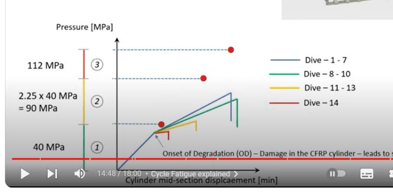
From yours this is an interesting graph and his calcs basically show that their predicted collapse pressure new was about 56MPa, with a dive depth of 4000m (40 Mpa). So at best a FOS from operating to COLLAPSE of 1.4. As the commentary says, this only works when you have full knowledge and reliability of the data used in the analysis.

Then as the number of deep dives increased that FOS reduced until it failed. But 1.4 FOS is absolutely nuts.

Screenshot_2024-09-19_095854_vtcuji.png


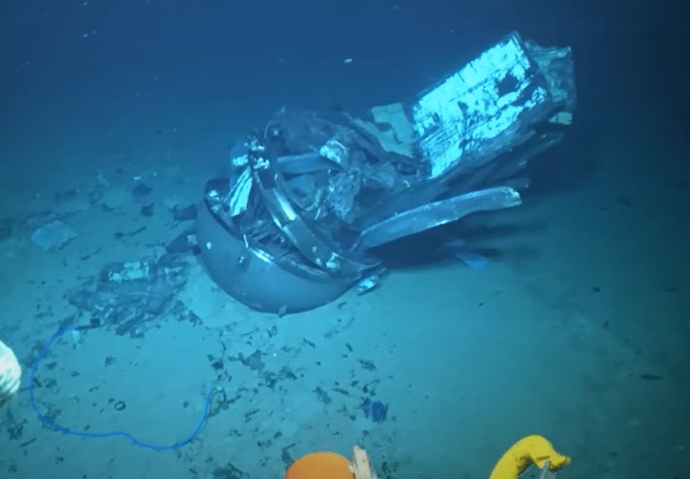
The second set of photos and analysis seems to indicate that the failure point was at the entrance end where the titanium ring met the CF hull and has been speculated on here previously as being a crucial and likely source of the failure point. The photo below shows the far end with all of the CF material basically compressed into the end shell. The other end cap and the dome blew out in the collapse.

Screenshot_2024-09-19_100955_e0fsun.png


Remember - More details = better answers
Also: If you get a response it's polite to respond to it.
 
Littleinch - yes, the simulation appears to have chosen/calculated an initiation of implosion at the front dome interface. The actual evidence contradicts that mechanism. After seeing the photos of the actual debris site, I understand why no CFR hull components were present in the sea surface recovery photos - there is no hull remaining! The hull suffered a complete shattering. Quite sobering. I have to wonder if the lack of a precedent implosion wreckage of a CFR hull caused the OceanGate team (as guided by Stockton Rush) to underplay/downgrade the severity of an implosion event? Any engineering effort to develop a similar vessel will now have explicit evidence of the enormous risk involved.
 
Since the OceanGate team never sent an actual unmanned Titan to full Titanic depth until failure, each of the manned dives probably increased their confidence level with the hardware and caused a normalization of implosion risk. All the creaks and snaps of the hull became accepted - similar to the acceptance of the sounds of an old but trusted vintage automobile. Unfortunately, their risk analysis apparently discounted buckling failure is instantaneous and testing to failure with a full size vehicle would have provided much insight into the safety of the design.
 
That material that is sticking out of the front ring and dome looks to be where the high-pressure air cylinders were stored under the floor.

The testimony of Tym (forgot last name) indicates his belief that the hull was being squeezed in a way that local bending at the interface with the wring was being resisted by the tension in the adhesive, but that the adhesive was, dive after dive, coming loose circumfentially until it could no longer resist the shear load from the differential squeeze between the carbon fiber hull and the titanium ring, leaving only the small step in the ring. When it reached a point of critical damage the remaining adhesive failed, momentarily transferred the load to the small step, which he observed had been completely sheared, indicating an event so rapid the failure could not have started at one location and progressed.

He observed that at the rear the progressive shear of the ring was observed as a curlicue of metal that remained attached, indicating a secondary and slower failure.

This isn't an initial buckling failure, it appears that the diameter of the carbon fiber hull was being elastically squeezed to a smaller diameter than the elastic squeezing of the titanium end caps followed by the inability of the eventually unsupported open end of the tube to remain stable after the connection was sheared off.
 
3DDave - is Tym's testimony part of the MBI? So he is saying the failure was caused by the inner wall of the end ring that formed the engagement channel for the CFR tube sheared off (collapsing radially inward)? This would mean the predictive modeling did not account for a failure mode that is well understood. Cyclical stress to the titanium hoop of the engagement ring should have been seen. (I am assuming OG used an analysis program more involved than something like Solidworks Simulation or Autocad Inventor's built-in). Of course, the model may have been influenced by expectation of continuous adhesive bonding to provide control of the bending moments created at the engagement grooves of the end rings. But the fault analysis should have included evaluation of loss of adhesive bonding.
 
And the failure modes missed in the computer modeling would been more likely recognized if a full size vehicle had been tested to failure with repeated dives to Titanic depth.
 
Does the computer modeling account for hydration of the adhesive joint? We saw the assembly video. The joint was not properly prepared. The design may have been sound, all of the computer modeling may have confirmed this. It doesn't matter how strong the design is if you don't tighten the bolts.

Why did the USCG allow so much effort to be wasted on speculation and misdirected studies before releasing these images?
 
Why would / how could a computer model include that?

As to testing a full sized vehicle - they did, and it lasted for a largish number of cycles, n-1, as it turned out.

What they didn't do was perform any inspections of the joint to see if it remained OK. That testing could be done on a smaller sample that applied similar amount of tension and then put that under the same sort of pressure to simulate infiltration into the matrix. One can generate conditions more severe than a full size test in order to discover failure modes for the bond.
 
Certainly scale testing could have been done (and may have been done to some level) to develop guidance but I don't think OG had any feel for fatigue failure modes of the hull. Had they tested a full size hull to failure at Titanic depth, the n= 14 limit might have been recognized.
 
"Piccard's original pressure sphere was built by Acciaierie, Terni of steel forged in two hemispheres and welded to form a sphere 2.4 metres (7.9 ft) in diameter and 89 millimetres (3.5 in) thick,[7] This pressure sphere was replaced in December 1958 with another cast by the Krupp Steel Works[8] of Essen, Germany in three sections; an equatorial ring and two caps, which were finely machined and joined by the Ateliers de Constructions Mécaniques de Vevey. The new sphere was also steel, but smaller at 2.16 metres (7.1 ft) diameter and with thicker walls, at 127 millimetres (5.0 in),[5] calculated to withstand the 1,250 kilograms per square centimetre (123 MPa) pressure at the bottom of Challenger Deep plus a substantial factor of safety."

From:
And, quoth:
"On 15 November 1959, as the Trieste with Piccard and Project Nektron director Andreas B. “Andy” Rechnitzer on board completed a record dive of 18,150 feet, a glue joint on the bathyscaphe’s pressure sphere failed because of unequal expansion during the temperature change from the frigid depths to the tropical surface. Its center section was offset at one end by about 1/8-inch. The sphere's components needed to be realigned, rejoined, and resealed, but the mission's forward base at Guam did not have the necessary facilities."
From:
And again,
"A preliminary dive to 4,900 feet was satisfactory, but the next dive to 18,150 feet was marked by water leaking into the sphere. The sphere had been made in three parts, a center ring with a cap on each end. The joint between the parts was machined perfectly and then bonded together. Upon arrival at the surface, the epoxy bond was damaged, however, and emergency measures were employed in order to enable the project to continue safely. The three sections were held in place by steel bands, and a new sealing system was imposed on the joints. Several more test and practice dives were made, and the sphere was considered satisfactory. The next stop was the Challenger Deep."

So not "slapped" together, rather "machined perfectly and then glued together".
 
New documents have been added to the Marine Board of Investigation website, including a very interesting transcript of the meeting between David Lochridge, his boss, and Stockton Rush.

A few points:
1. Rush wouldn't even give Lochridge some of the certification / documentation that he did have, possibly because he thought they would have scared him even more than not being able to see them.
2. Rush claims emphatically that everybody else is wrong and carbon fibre is actually better in compression.
3. Rush is sure that he won't die on the sub because any failure will be gradual and he'll have enough time to surface before any implosion. Rush stated "It doesn't just implode. It screams like a mother before it implodes." He claims that other experts have also told him that he'll hear it before it fails.
4. Rush claims that "everything [the Spencer PhD engineer] has told us has been wrong", but he still insisted on using the hull designed and built by Spencer.
5. Rush admitted that he had no idea what depth the hull would actually be good for.
6. Rush doesn't seem to have given much consideration to the possibility of the bond between the hull and end caps failing, or that this would likely be a quick failure without much warning from the acoustic monitoring system (i.e. it probably won't "scream like a mother" before this type of catastrophic failure).
7. Rush seems to think that voids don't really matter and are unlikely to grow in a significant way because he has the right glue between the layers.
8. Rush doesn't value traditional NDE because he doesn't know what to do with the data. He thought the acoustic monitoring data would be useful for preventing failure, but as pointed out by Lochridge, Rush had no baseline for the acoustic monitoring data, and thus no way to tell if a sound means impending doom or is just a "whale fart". Rush claimed they hired a PhD in statistics to help them figure out the meaning of the sounds, but there doesn't seem to be any plan for this, and they won't know what sounds are indicative of failure until after a failure has occurred.
 
Admittedly I haven't been following all the docs super closely, but they didn't even take a replica to failure as some sort of baseline "training" of the acoustic monitoring program that they were basically swearing to?
 
Admittedly I haven't been following all the docs super closely, but they didn't even take a replica to failure as some sort of baseline "training" of the acoustic monitoring program that they were basically swearing to?

Rush believed that testing to failure was detrimental to the advancement of the state of the art, i.e., the rigorousness of testing prevented innovation.

Obviously, he was an idiot in that regard, and killed 4 other people in his insanity.

TTFN (ta ta for now)
I can do absolutely anything. I'm an expert! faq731-376 forum1529 Entire Forum list
 
TUGBOAT said:
Does the computer modeling account for hydration of the adhesive joint?
3DDave said:
Why would / how could a computer model include that?

Tugboat, it is not possible to model interfacial degradation due to hydration.

3DDave. The reason for addressing hydration is that it results in one of the most common forms of bond failure.

ALL adhesive bond design methods inherently assume that the bond is sound and the processes are reliable enough to prevent hydration. This assumption is further weakened by a widespread belief as proposed elsewhere here, that demonstration of strength by testing of samples or full scale tests will provide assurance of ongoing structural integrity. If a surface that is susceptible to hydration driven interfacial failure (adhesion failure) any demonstration of strength will only assure structural integrity at that given time. It will NOT guarantee future strength because hydration is dependent on TIME since manufacture, as well as secondary factors such as exposure to water, temperature and possibly even exposure pressures.

The best way to manage this form of failure is to avoid it altogether by demonstration that your surface preparation processes can provide adequate resistance to hydration based on test results from wedge testing using ASTM D3762.

I note SWComposites posting of 24 Sep. Is that a photo of a sample from the manufacturing process...really? Are you saying that this sample was taken from the rubble, or was it from a previous test article? If it was from the rubble, then I am not surprised it failed. If it was from a previous test article, then they knew about how bad their processes were and should have had the sense to halt production until they sorted out the mess.

Does anyone know how the laminate was cured? Was it cured at room temperature, or did they use autoclave processing at elevated temperature?

Regards

Blakmax
 
Hull was cured in an autoclave after every 1" of fiber wound. Strain and acoustic sensors, and their wires, being wound between layers.
 
blakmax said:
3DDave. The reason for addressing hydration is that it results in one of the most common forms of bond failure.

I didn't say it should not be considered, I'm saying that there aren't any individual molecule level FEA programs to do it; even multiphysics programs require someone to pre-determine the exact effect. It also doesn't help anything because if hydration is a problem it should not be used at all for the submersible application.

Which is why

3DDave said:
That testing could be done on a smaller sample that applied similar amount of tension and then put that under the same sort of pressure to simulate infiltration into the matrix. One can generate conditions more severe than a full size test in order to discover failure modes for the bond.

was suggested rather than FEA.
 
"I note SWComposites posting of 24 Sep. Is that a photo of a sample from the manufacturing process...really?"
I understand they wound the whole hull, then trimmed the ends to bring it to exact length, and that was one of the trimmed pieces. I think the guy-that-was-fired said he had taken that picture, but that the sample had been disposed of in the meantime.
 

Part and Inventory Search

Sponsor