Continue to Site

Eng-Tips is the largest engineering community on the Internet

Intelligent Work Forums for Engineering Professionals

  • Congratulations KootK on being selected by the Eng-Tips community for having the most helpful posts in the forums last week. Way to Go!

Tourist submersible visiting the Titanic is missing Part 2 69

For cavitation, is it the temperature? or the impact of the fluid from the opposite side of the 'bubble'? or a mix of both?

-----*****-----
So strange to see the singularity approaching while the entire planet is rapidly turning into a hellscape. -John Coates

-Dik
 
I'm not sure if it has been exactly determined. My thought is that its just the high total energy impact which ruptures the molecular structure of the surface crystals and strips them away bit by bit. Surely the most common and damaging aspect of pump and maybe ship's propeller operations. Even a small amount of energy is a super high flux, due to the extremely short focus time.

Those pistol shrimp in the link I posted above are deadly. 250dB, twice as loud as a jet engine and 5000°C temps and let there be light. Good thing that they aren't a bit bigger and living in close proximity to humans. It's surely the underwater weapon of choice.

Not sure if this video has made it into the thread yet. I don't recall seeing it. Some good comments from an experienced CF engineer in the comment section too.
Break time:
--Einstein gave the same test to students every year. When asked why he would do something like that, "Because the answers had changed."
 
1503-44 Good YouTube video by Beyond Engineering. There is a lot of junk posted on YT, this video is worth watching.
 
This follows on the 'shirt tails' of the above youtube and is also interesting... There was a 'deep hole' project when I was in geological engineering called the Moho (sp?) project.


-----*****-----
So strange to see the singularity approaching while the entire planet is rapidly turning into a hellscape. -John Coates

-Dik
 
My question is about the compression/decompression rates of dissimilar materials that are attached to each other. I have no idea, but I imagine that titanium and carbon fiber will compress and decompress at different rates. So could there have been gaps in the titanium/CF interfaces created over time during ascents and descents? And what about the effect of salt water on the bonding material in those gaps? [ponder]
 
I think it can be a problem, but it is probably minimuzed when the interface is in compression.

--Einstein gave the same test to students every year. When asked why he would do something like that, "Because the answers had changed."
 
Jedidad said:
I imagine that titanium and carbon fiber will compress and decompress at different rates.

E for Titanium: ~50 to around 120 GPa, depending on alloy. I suspect an assumption toward the upper and of that range is safe, it's unlikely their domes were pure titanium. I don't believe we know exactly what alloy they used, but I suspect 6Al-4V or something similar. E for low-ox 6AL4V is around 115 GPa.

E for carbon fiber: very reliant on construction. The generic number is around 200GPa, but it can be as high as 500+ GPa.

There's another variable though - stiffness is a function of bulk material properties and section dimensions. I'd argue that for a structure like this, matching strain at design load between mating parts would be a major part of engineering best practices for a safe design. ESPECIALLY if that design involves a field-made adhesive joint. You'd want the absolute lowest possible amount of shear stress on that adhesive to give it any kind of chance.

I'm too lazy to dig out Roark's and look it up, but it's possible that a hemisphere with the edge supported is a stiffer geometry than an edge supported hollow tube, in which case maybe the composite section was strain matched despite the bulk stiffness of the carbon shell being likely much higher than that of the end domes. Given the level of engineering diligence displayed elsewhere, and the fact that the hull components were not all designed by the same firm, I would doubt that level or coordination between mating parts was in place.
 
I too think the different response of the Ti end caps and CF hull to huge external pressure may have factored in here. If the end caps had more strain, that would have been transferred to the CF, and increased stress there. Or to the epoxy joint.

No substitute for repeated deep dives with monitoring, then dive to failure.
 
Waross, It's not just 400x compression ratio, but potentially much higher (orders of magnitude more) due to the momentum of the water column accelerating to fill the void, that accelerated water column doesn't just stop at the static pressure equalization, it has to be stopped by an increasingly smaller pocket of air. The bubble/collapse then rebounds several times, decaying in peak pressure/temperature each time. (see first link below) Water hammer is scary stuff. As 1503 said, very high temperatures are instantaneously achieved (not during cavitation per se, but during the collapse and rebound of the cavitation bubble). There is documented release of visible blue light from the point of collapse (sonoluminescence) - see 2nd link.

high speed film of underwater detonations -
 
Love those older videos. No BS, no narrative, just a really dull narrator backed up with fascinating information.
 
Jedidad said:
And what about the effect of salt water on the bonding material in those gaps?

Read my previous posting on adhesive bond failure mechanisms and interfacial hydration. Salt exacerbates hydration. So if their surface preparation is deficient, the operating environment will definitely find the deficiencies.

Another issue from the adjacent discussions: There will be thermal stresses generated during the cure cycle due to the different thermal expansion coefficients for CFC and titanium, but there also is a contribution from the relative thicknesses and moduli. It is actually possible to design a bonded joint between thin materials such that the failure will always occur outside the joint. However in this case the CFC is so thick and stiff, that the failure will ALWAYS occur through the adhesive if the surface preparation is valis and resists hydration, but if the surface preparation is inadequate, the failure will occur at the interface, leaving the adhesive layer intact in some regions. This is a very weaK failure mode.

The real issue is that the very thick CFC cylinder butts up to the end cap. I can not conceive of any circumstances where the adhesive between the faces of the CFC and the titanium would survive the extreme compression stresses as the pressure on the end caps is transferred to the CFC shell.Then the next excursion would result in water ingress into the joint. A bit of time between excursions and hydration would ensure that the bond would not survive if the interface is weak.

With some design effort, together with some manufacturing ingenuity, it would possibly have been possible to design the joint such that the adhesive could actually carry the loads. A multiple step fir tree joint may have been capable of carrying the loads. But a single overlap and one step butt joint could never carry the load without the adhesive being the critical element in the joint.

Regards

Blakmax


blakmax said:
...I can not conceive of any circumstances where the adhesive between the faces of the CFC and the titanium would survive the extreme compression stresses as the pressure on the end caps is transferred to the CFC shell...

Just curious, what are typical bearing strengths for engineered epoxies like the Hysol EA9xxx series? In theory the bearing stresses at the interface between the Ti ring and the carbon barrel should be around 20ksi.
 
You can assume a generic epoxy is going to have a compressive strength of 8,000-10,000 psi. There are varieties that can double those values.

Much depends on the specific product they used.
 
Other than the compression failure of the epoxy. What effect would that have on the waterproofness of the joint? Wouldn't it simply act as 'filler'?

-----*****-----
So strange to see the singularity approaching while the entire planet is rapidly turning into a hellscape. -John Coates

-Dik
 
Chockfast Orange comes in at 19,000 psi and it's engineered specifically for compression loading.
 
19,000?

As I posted above...
Wall stress: 55,000 psi compression-
Long stress: 29,000 psi compression on a 5" thick wall. Someone said the joint might have less bearing surface, which could double that.
Max shear +/-13,000 psi
(neglecting radial stress)

--Einstein gave the same test to students every year. When asked why he would do something like that, "Because the answers had changed."
 
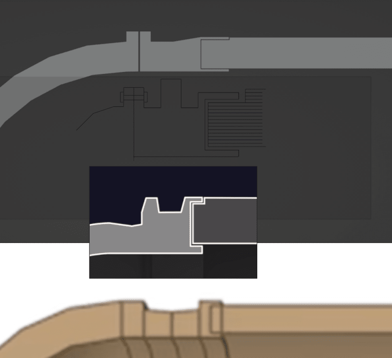
I updated my cross-section of the hull based on more recent images and videos. Here it is along with some others I have seen:

1 - at top is my latest impression (I think my interface ring is slightly too wide from left to right and I don't think the bolting flanges are necessarily of different widths.)
2 - my earlier design
3 - the NYT's design shown in this article: 4 - the design from the ANSYS simulation video
2023-07-21_10_24_29-Blender__C__Temp_titan.blend_w5qvf2.png
 
rodface said:
I updated my cross-section of the hull

Looks pretty close to me- although I think the slot in the intermediate ring is much shallower than that. From the videos of them making up the adhesive joint, it looked like the depth of that feature was maybe 1" at most.
 
So... from 31ms to 38ms... neat article.

-----*****-----
So strange to see the singularity approaching while the entire planet is rapidly turning into a hellscape. -John Coates

-Dik
 

Part and Inventory Search

Sponsor