Continue to Site

Eng-Tips is the largest engineering community on the Internet

Intelligent Work Forums for Engineering Professionals

  • Congratulations KootK on being selected by the Eng-Tips community for having the most helpful posts in the forums last week. Way to Go!

Tourist submersible visiting the Titanic is missing Part 2 69

One question to ponder;
Did the recovery crews partially dismantle the parts for easier/safer handling?
We saw a lifting sling through the porthole and suspected that the window had failed.
Then we saw what looked like one of the titanium rings, that appeared to be separate from the end bell.
So, was the failure so violent as to rip an end ring free from the titanium hemisphere or did the recovery crew remove the bolts while onboard the recovery vessel to make subsequent handling safer and easier?
If the recovery crew did not remove the bolts, the implication is that both the glue joint and the bolts failed simultaneously, leaving the ring orphaned.
While possible, there is really no force on the ring itself that would lead to failure, and once the bolts failed that would relieve any force on the glue joints and if the glue failed first, that would relieve any force on the bolts.

The profile of the sound waves piked up by the navy may shed some light on the failure progression.
For a hull failure, the wave form may be a single burst or peak, possibly followed some time later by sounds of the pieces landing on the bottom of the sea.
For a hull failure followed by a water hammer failure I suspect a first burst of sound as the window fails and milliseconds later a greater sound burst as the end hemisphere fails.
Again possible faint sounds of pieces hitting the bottom.
When it comes to determining the failure progression for the information available to us, we are in uncharted water. (grin)


--------------------
Ohm's law
Not just a good idea;
It's the LAW!
 
My question from the first thread, anybody got opinions?

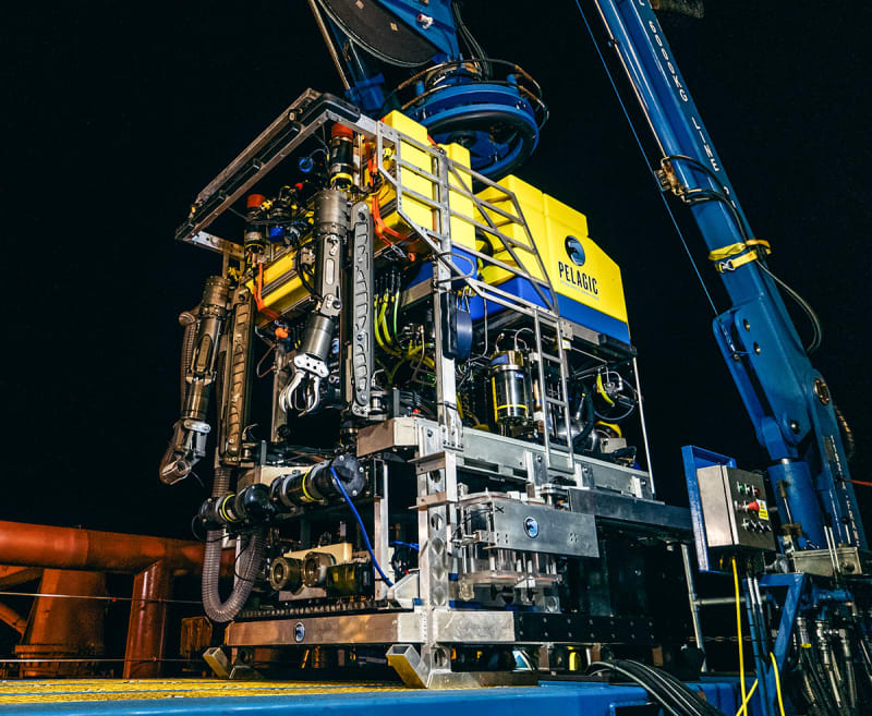
I haven't seen anything on how these pieces are brought to the surface. ROV's? Lift bags? Crane with 2 1/2 miles of wire?

I don't see any real disassembly at 12,500 ft.

The problem with sloppy work is that the supply FAR EXCEEDS the demand
 
You need some extremely high pressure air to make a lift bag work.
It still may be the best way.
Possible, bag to the surface and then retrieve with the rig used to launch the submersible.
Once out of the water on the retrieval platform, disassembly before further handling.

--------------------
Ohm's law
Not just a good idea;
It's the LAW!
 
Air at sufficient pressure is doable - the challenge is going to be getting sufficient volume.

I'd consider a lifting bag full of petrol sent to the bottom over a disposable ballast with a drogue to control the ascent rate.

A.
 
Violent is an understatement. There's not much that can withstand a 600mph water jet and especially what follows it.

--Einstein gave the same test to students every year. When asked why he would do something like that, "Because the answers had changed."
 

self-disassembly?


Just overcome the water pressure, would there be any increase if the fabric stresses due to the high pressure, or just the (inflation - water) pressure? Are there some other issues that have to be addressed?

-----*****-----
So strange to see the singularity approaching while the entire planet is rapidly turning into a hellscape. -John Coates

-Dik
 
waross said:
If the recovery crew did not remove the bolts, the implication is that both the glue joint and the bolts failed simultaneously, leaving the ring orphaned.
While possible, there is really no force on the ring itself that would lead to failure,

This was a catastrophic implosion at 3600m deep. The shock could easily have blasted the end caps off in a violent manner, separating the ring in the process. Likewise the window.
 
Much speculation, not much to go on. Looking forward to "Tourist Submersible... Part 18" :)

The problem with sloppy work is that the supply FAR EXCEEDS the demand
 
As requested, posted from old thread.

Regards

Blakmax

Ok

I had my money on the apalling Tsai-Hill or Tsai-Wu failure criteria giving a totally incorrect prediction of compression-compression strength. I reserve that opinion, but now based on Tugboat's pictures and Rodface and IRstuff postings above, I would add real concerns about adhesive bonding issues. In Tugboat's image, I do not see any significant fore-aft overlap for the adhesive bond. Surely they did not rely on the bond between the vertical face of the five inch composite and the titanium end cap to conduct load. Even people of very restricted engineering knowledge understand that the first rule of bonded joint design is that you NEVER rely on bonds that even have a minor risk of tension loading.

My next concern is the overlap length shown schematically in Rodface's posting between the end fitting and the composite shell. Does anyone have dimensions? One of the most significant stupidities in adhesive bond design is to use the lap-shear strength as determined by tests such as ASTM D1002 to design the overlap length for bonded joints. Further, the strength of adhesives changes dramatically with temperature, so I just hope they provided test data at the low temperatures at depth. Typically, at low temperatures the adhesive is very stiff and the strength is higher, but the elastic modulus is also very high which results in a very low strain to failure.

My next concern is in relation to the surface preparation procedures for the titanium end caps and also for the former shown by IRStuff. Please understand that adhesive bonding is a chemical process that relies on the formation of chemical bonds between the adhesive and the surface of the metal or composite resin. Surface rough ness is a secondary issue. Now, everyone knows that the surface must e clean, so that surface contaminants do not interfere with the chemical reaction. But a clean surface is not a sufficient condition. The surface must also be chemically reactive so that chemical bonds are actually able able to form. Such a treatment will provide a strong bond in the short term.

However, there is a third requirement that many people overlook. Many metals have an affinity for the development of hydrated oxides, for example aluminium (Ok, for the US readers aluminum) will form Al2O3 as soon as the surface is exposed. Over time this surface has a tendency to hydrate to form Al2O3.2H2O. For this reaction to happen, any adhesive bond to the original oxide layer must dissociate so that the hydration reaction can occur. This is the cause of interfacial adhesion failure of the bond. Hydration is exacerbated by immersion in water and the addition of salt. There are essentially three adhesive failure modes:1 cohesion, where the adhesive fractures leaving a layer of adhesive on both surfaces. This is a high strength mode of failure. 2. Adhesion failure where the adhesive separates from a substrate at the interface due to hydration. This is a very weak mode of failure. 3. A mixed-mode failure which is a variable mixture of cohesion and adhesion. This mode occurs as interfacial hydration is happening, with the strength degrading as hydration progresses. I am concerned with the degree of adhesion failure shown in the picture shown by Tugboat.

An essential requirement for longer term bond durability is a treatment applied to the surface to demonstrate that any surface preparation provides adequate resistance to interfacial hydration. The best test for this is the wedge test such as ASTM D3762.

So, I have grave concerns about the composite design, the adhesive bond design and the adhesive bond surface preparation processes. I don't think the company could have PAID ME enough to encourage me to take the trip.

Regards

Blakmax

 
Lifting bags are open bottomed. More like lifting socks.
As they ascend the air expands and vents out the bottom rather than building pressure that would rupture a closed bag.
Commercial compressed gas cylinders top out at a working pressure of about 2500 psig.

Fun with numbers: (neglecting the weight of the compressed air. The weight of the air would only make things worse.)
Displacement of 1920 lbs of water requires a volume of 30 cubic feet.
So a sock of about 3 ft. dia. by 4.25 ft. high.
Now if we use a tank 3 ft.in dia. by 8.5 ft. high pressurized to 12000 psig, once the tank is opened to the sock, the pressure will equalize at 6000 psig in both the tank and the lifting sock.
Let's neglect the bouyancy of the compressed air tank. It will probably be heavy enough to sink.
So we are looking at a special build tank serving at almost 5 time the pressure of commercially available tanks, for a one time lift.

I think that a simple tank filled with a light liquid and using disposable ballast is the way to go.
Naptha weighs 7.42 pounds per Imp gallon compared to sea water at 1.025. at 10.25 pounds per Imp gallon.
Each imperial gallon of naptha will have a bouyancy of 10.25 - 7.42 = 2.83 pounds.
A used (cheap) 5000 gallon storage tank filled with naptha will have a bouyancy of about 5000 lbs.
The challenge is to connect the tank to the object to be lifted in such a way that the tank is not damaged.
A cable halter and vertical orientation will probably do the job.


--------------------
Ohm's law
Not just a good idea;
It's the LAW!
 
another article...


-----*****-----
So strange to see the singularity approaching while the entire planet is rapidly turning into a hellscape. -John Coates

-Dik
 
Dismantlement would be a gross violation of what I would assume to have been instructions to the recovery crew, which is to PRESERVE evidence.

Any intentional retrieval or post-retrieval dismantling would be grounds for firing everyone involved. If they did dismantle anything, how would anyone know what actually happened? Did the dismantlers measure the force required to remove the porthole, for example? Did they wind up creating additional damage in prying the porthole off? And wouldn't it be silly, that they couldn't come up with a different way of hoisting the end cap without damaging the evidence?

TTFN (ta ta for now)
I can do absolutely anything. I'm an expert! faq731-376 forum1529 Entire Forum list
 
Presumably, if the porthole was still in place, it would not be the initiator. Even if it was, that condition was changed by the removal of differential pressure during the accident. Any removal would be documented the way that the location and orientation of each part on the sea floor was prior to removal from there.

They were working on a $100-$500k per day recovery effort with equipment not designed with the intent of lifting such items. DailyMail (for what that is worth) claims $6.5M was spent on the effort. Spending more time to make a more sophisticated effort seems unlikely. Those recovery resources are needed elsewhere.

I do expect that everything was separated by the implosion, particularly the port hole, making this point moot.

It's a surprise they managed the task. It will be interesting to find out what they did.
 
"I haven't seen anything on how these pieces are brought to the surface. ROV's? Lift bags? Crane with 2 1/2 miles of wire?"
The ROV's used to find it were tether-operated, I thought, so presumably, grab a piece and hoist both together>
 
Odysseus_ttt3xu.jpg


The recovered debris has been dissembled and cut, when you look closely. Bolts missing, frame pieces cut. Nothing is bent or mangled.
No sign of any carbon fiber hull pieces. Missing is the titanium rear end bell and ring. I'm not sure how heavy that would be, but likely the ROV attaches lifting cables? ROV used Odysseus 6K

I am surprised at how much trouble the Internet armchair analysts have understanding a carbon fiber composite cylinder in hoop compression. Everything out there is the opposite - a pressure vessel, common in MECE textbook, examples, diagrams. No other application is even close to that of a deep sea sub hull. A vacuum tank delta P is 1atm, not 377atm. I can't see CF being suitable for the application at all.
 
I was concerned when I read that the design of the composite cylinder appears to have been subcontracted to the manufacturer, who then appears to have used an add on FEA program to a well known modelling program for the analysis.

The entire system of cylinder, rings, end caps, porthole etc therefore appears to have been designed as a series of parts, and not as a whole. The risks of these plug and play stress analysers in the wrong hands have been well documented for years.

Does anyone know if the analysis would likely have used thin shell composite elements, whether this is realistic for a thick skin, and whether this would accurately model the transfer of stress through the thick cylinder due to the pressure loading being applied to the outer face only?
 

Part and Inventory Search

Sponsor