Eng-Tips is the largest engineering community on the Internet

Intelligent Work Forums for Engineering Professionals

  • Congratulations waross on being selected by the Tek-Tips community for having the most helpful posts in the forums last week. Way to Go!

Tower crane peer review

Status
Not open for further replies.

SM89

Civil/Environmental
Jul 2, 2013
15
0
0
US
I am new to doing peer review on tower cranes. The tower crane stands 260ft tall with a massive foundation. I see the designer has used crane dead load & weight of crane footing in arriving at reactions and overturning moment. In my opinion wind loads should be included to obtain base reactions, i could be wrong. Please share your valuable input.. If i am supposed to check for wind loads what would be a quick way to get the reactions without having to do the entire calculations myself, because this is only peer review. I just want to get a feel for structural capacity of footing with wind loads on tower crane.

Thanks,
SKM


Replies continue below

Recommended for you

Is the crane braced at floor levels? Moment will be eliminated. Can you ask the designer how it was designed?

Dik
 
You should include wind load to the maximum recommended by the crane manufacturer. Get a copy of Cranes and Derricks by Shapiro. There is an extensive section on tower cranes.
 
Chicopee, am not sure about the free standing height. Crane used is Terex CTT 561A-20, i do not see the specs calling out max unbraced free standing height but i did google it and found out through biggie cranes and rigging company's website mentioned as 344ft (Max. freestanding hook height). Again, i do not see bracing any where on the drawings provided to me.


Thanks
 
TC_footing_pic_cwanfu.png
RISA_load_clarification_zka8mm.png
Free_standing_heights_cr3foa.png
 
SM89 - In the US and many other countries there are restrictions on tower crane use in windy conditions. The manufacturer usually will publish wind limits for each model. This info will be in a crane's detailed operating manual, not in readily available "sales" type specifications.

A widely accepted standard is to take a crane out of service when wind speed reaches 20 meters/second (45 miles per hour). When higher wind speeds are predicted, the crane may be secured with guy wires, or even lowered.

Don't perform wind speed analysis as if the crane is a fixed, unchanging structure (for example, a building). Find out what steps are taken in windy conditions for this crane model. Because action is taken, wind loads are too low to govern.

[idea]
[r2d2]
 
SRE: Not sure, but I understand the rating for taking the crane out of service is typically for 10m above grade and wind speed must be adjusted for the height and for something as tall as 260', the max wind speed might be 25 or 30 mph.

Dik
 
Dik, thanks for sharing that piece of information. I did go through the crane spec in detail and found out that the spec provides base reactions for In-Service and Out-Of-Service conditions and also specifies that wind loads for out of service condition has been taken from FEM 1004.
Yet to read thru FEM 1004 to find out what wind loads have been used in arriving at the base reactions.

Thanks,
 
My experience is that for hammerhead cranes the wind load cases are typically more critical than the maximum in service loading (i.e. lifting something in simple terms). For a luffing crane typically its the lifting stuff that is more critical than wind loading as there is less counterbalancing going on (hammerhead cranes I have dealt with have moving counterweight on the back span vs fixed counterweight on a luffing crane).

Not sure where you are but in NZ/Australia we have a code (AS 1418) that outlines all the load combinations that a tower crane foundation must be designer for, there are about 7 load combinations to consider all with varying load allowances. I'm sure where ever you are based there is a similar code with similar load cases.

The thing is usually you have no idea what the loads the manufacturer gives you are based on. They can give you specific loads for specific loadcase, but usually you pay for their engineering team to look at it.

See below for example

Capture_mx9beb.png

Capture1_tjmkqa.png
 
Highly off topic, but I was curious since I have never seen anything so massive before: why no vertical ties in this large mat foundation? Is shear not a concern?

Maybe a 6'-0" thick footing can get the job done from a shear perspective, but I have no gut feel to rely upon due to the magnitude of this crane and loading coming down on it.
 
Agent666, i live in US. The crane supplier has provided me overturning moment, vertical and horizontal loads for in-service and out-of-service conditions. But there is no break down on the factors or coefficients used to arrive at those values (Although they mentioned in a footnote that wind loads have been considered for design). I did go through their foundation calculations, apparently the footing has huge uplift force and the designer has used piles to resist uplift tension. Anyway designer has not used 1.5 safety factor on moment so i am gonna have to ask them to redo their calculations including the safety factor for over turning and provide detailed break down on the moments and laods published on their drawings.

Thanks

 
sticksandtriangles, i checked for punching shear,it looks fine. One reason is the depth of footing and other reason is concrete compressive strngth is 6000 psi. So my check against unity is close to 0.6, but i am not sure if the code requires to provide minimum reinforcment regardless. Does anyone know about that ?

In normal spread footing its not common to use vertical stirrups. Advise !!.

Thanks,
 
There is so much to comment on this foundation that it is hard to know where to start. So, will be begin at the bottom:

TC_footing_pic_cwanfu-1_lcuedz.png


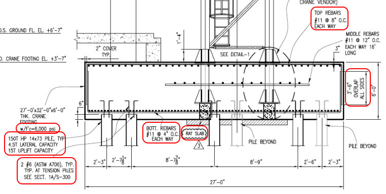
1. Did you receive the geotechnical report? Design load of 150 tons is a lot for an HP 14x73... especially when any settlement will cause major problems. Also have the 15 tons uplift per pile. Would be nice to see the backup for these high values.

2. Will any to these piling, or similar piling on the jobsite, be load tested to verify accuracy of the geotech recommendations (testing for both for bearing and uplift)?

3. How many piles are there? I see six, if that is all or anywhere close to to all, there is essentially no pile redundancy. Not all driven piling perform as expected.

4. The 15 tons uplift / tension pile is resisted by 2 each #6 rebar in tension... not much steel. At a minimum review the connection of the rebar to pile and rebar (tension) anchorage in the concrete.

5. An HP 14x73 has a crossectional area of 21.4 in[sup]2[/sup]. With the 150 ton design load the pile is (theoretically) compressing the 6 ksi concrete with 14 ksi of pressure. There is controversy if this type loading is a problem, or not. I believe that this type high loading is ok... under the right conditions. This design does not meet what I would consider the "right conditions". Steel plates on the pile tops are another solution... but one that has it's own set of serious drawbacks.

6. Let's move on to rebar, the designer has selected #11 bars for what appears to be one reason - the largest bar size where lap splices are permitted. This foundation is begging for #14 or maybe #18 bars... with their mechanical or welded splices. Using #11 rebar results in a foundation "choked" with a large number of rebars. Look at the bottom rebar mat - #11 @ 4" O.C., Each Way. All the concrete that goes below that mat, to the critical pile bearing area, has to pass though a "screen" that has "hole's just over 2 1/2" square. Yes that probably meets code on concrete aggregate clearance. But don't count on getting well consolidated concrete below the bottom mat.

7. The top mat, #11 @ 8" O.C., Each Way, is better, but considering virtually all the concrete has to pass though this mat, expect problems. Problems made worse since the concrete placement under the bottom mat (See #6, Above) has to be worked though this mat, too.

8. The #11 lap splices are troublesome. First, is a 42" inch (3' 6") long enough - that's a question, I don't recall the answer. The top mat #11 bars @8" are turned down. The bottom mat #11 bars @4" are turned up. The perimeter is a virtual wall of rebar, and there are twice as many upturned bars as downturned bars. Ok, just upturn every other bar in the bottom mat - but that is just a half-way solution to the rebar crowding.

9. The top rebar mat weights about 9 tons, the bottom mat about 18 tons. Has the designer addressed the structural support system for these mats? Better still, is the Contractor required to submit (for approval) detailed plan on how to do this? Note that any reasonable support method for the top mat will affect rebar placement locations of the bottom mat.

10. Along with the rebar mat support, consider how will the soil under the foundation carry the temporary load from the rebar supports. The designer shows a small "Rat Slab" (mud mat), but a full-size (structural) mud mat will probably be needed for the construction loads. Again, a design for the Contractor to submit for approval.

11. Now to the concrete, 6 ksi. Probably a lot of cement in the mix which means high heat of hydration for what is clearly mass concrete (6 feet thick). What controls are inplace for those issues? There is a lot of concrete (190+ yd[sup]3[/sup]) for one pour considering the rebar congestion. Cold joints are quite likely.

12. That's all I can think of for now. In summary, believe this foundation would benefit from more piling, larger size rebar, and lower strength concrete.


[idea]
[r2d2]
 
Thanks slideerarule, i did take your comments in to account.

Thanks everyone for sharing your valuable knowledge. Really appreciate all of you !!.

I have reviewed and sent a letter to client. I need to wait for them to address all comments and get back to me.

Thanks,
SM89
 
Hey just a quick question. Should the pile uplift force be multiplied by a safety factor of 1.5 and checked against the allowable capacity of the pile or checked against the ultimate capacity of the pile ?

Thanks
 
Need to find out what the stated "15 tons uplift capacity" means. Does 15 tons include a safety factor?

Concerning what multiplier to use, I assume this crane is not a permanent installation but will be used for a limited time then taken down. If so, criteria and factors from ASCE 37 "Design Loads on Structures During Construction" may be more appropriate than more strict requirements of ASCE 7 or building codes for permanent structures.

[idea]
[r2d2]
 
Status
Not open for further replies.
Back
Top