There is so much to comment on this foundation that it is hard to know where to start. So, will be begin at the bottom:
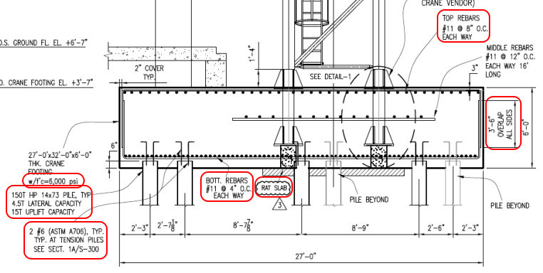
1. Did you receive the geotechnical report? Design load of 150 tons is a lot for an HP 14x73... especially when any settlement will cause major problems. Also have the 15 tons uplift per pile. Would be nice to see the backup for these high values.
2. Will any to these piling, or similar piling on the jobsite, be load tested to verify accuracy of the geotech recommendations (testing for both for bearing and uplift)?
3. How many piles are there? I see six, if that is all or anywhere close to to all, there is essentially no pile redundancy. Not all driven piling perform as expected.
4. The 15 tons uplift / tension pile is resisted by 2 each #6 rebar in tension... not much steel. At a minimum review the connection of the rebar to pile and rebar (tension) anchorage in the concrete.
5. An HP 14x73 has a crossectional area of 21.4 in
2. With the 150 ton design load the pile is (theoretically) compressing the 6 ksi concrete with 14 ksi of pressure. There is controversy if this type loading is a problem, or not. I believe that this type high loading is ok... under the right conditions. This design does not meet what I would consider the "right conditions". Steel plates on the pile tops are another solution... but one that has it's own set of serious drawbacks.
6. Let's move on to rebar, the designer has selected #11 bars for what appears to be one reason - the largest bar size where lap splices are permitted. This foundation is begging for #14 or maybe #18 bars... with their mechanical or welded splices. Using #11 rebar results in a foundation "choked" with a large number of rebars. Look at the bottom rebar mat - #11 @ 4" O.C., Each Way. All the concrete that goes below that mat, to the critical pile bearing area, has to pass though a "screen" that has "hole's just over 2 1/2" square. Yes that probably meets code on concrete aggregate clearance. But don't count on getting well consolidated concrete below the bottom mat.
7. The top mat, #11 @ 8" O.C., Each Way, is better, but considering virtually all the concrete has to pass though this mat, expect problems. Problems made worse since the concrete placement under the bottom mat (See #6, Above) has to be worked though this mat, too.
8. The #11 lap splices are troublesome. First, is a 42" inch (3' 6") long enough - that's a question, I don't recall the answer. The top mat #11 bars @8" are turned down. The bottom mat #11 bars @4" are turned up. The perimeter is a virtual wall of rebar, and there are twice as many upturned bars as downturned bars. Ok, just upturn every other bar in the bottom mat - but that is just a half-way solution to the rebar crowding.
9. The top rebar mat weights about 9 tons, the bottom mat about 18 tons. Has the designer addressed the structural support system for these mats? Better still, is the Contractor required to submit (for approval) detailed plan on how to do this? Note that any reasonable support method for the top mat will affect rebar placement locations of the bottom mat.
10. Along with the rebar mat support, consider how will the soil under the foundation carry the temporary load from the rebar supports. The designer shows a small "Rat Slab" (mud mat), but a full-size (structural) mud mat will probably be needed for the construction loads. Again, a design for the Contractor to submit for approval.
11. Now to the concrete, 6 ksi. Probably a lot of cement in the mix which means high heat of hydration for what is clearly mass concrete (6 feet thick). What controls are inplace for those issues? There is a lot of concrete (190+ yd
3) for one pour considering the rebar congestion. Cold joints are quite likely.
12. That's all I can think of for now. In summary, believe this foundation would benefit from more piling, larger size rebar, and lower strength concrete.
![[idea] [idea] [idea]](/data/assets/smilies/idea.gif)
![[r2d2] [r2d2] [r2d2]](/data/assets/smilies/r2d2.gif)


![[idea] [idea] [idea]](/data/assets/smilies/idea.gif)
![[r2d2] [r2d2] [r2d2]](/data/assets/smilies/r2d2.gif)
