Eng-Tips is the largest engineering community on the Internet

Intelligent Work Forums for Engineering Professionals

  • Congratulations waross on being selected by the Tek-Tips community for having the most helpful posts in the forums last week. Way to Go!

TP without a basic dimension? 5

Status
Not open for further replies.

rollingcloud

Aerospace
Aug 9, 2022
167
0
0
US
wwwwssfe_epa2l2.png


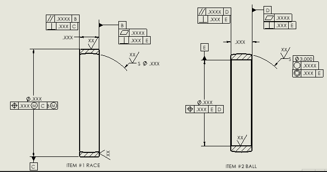
This was done by someone who I cannot reach out and ask. I am trying to make sense of his measurement drawing, it's not easy since I am a noob as well...
It has 3 axes as datums A, C and E, I am pretty sure that's not correct, one axis (datum C) should be enough IMO.
Also, none of the TP callouts have basic dimension.
Moreover, calling TP on the ball dia does not make sense to me.
Calling two flatness on the race seem to be not needed, especially if both surfaces are controlled by perpendicularity already.
Is form control on the ball OD a good idea?
 
Replies continue below

Recommended for you

Each part is individual - they each have a separate primary datum feature as does the assembly - datum features apply only at the part level and don't apply anywhere else. That makes 3.

None of them need a dimension because items that are nominally coaxial are defined as having a zero offset dimension which is not added to the drawing.

The flatness on the race is a refinement and the flatness tolerance value will be much smaller than the perpendicularity tolerance value.

 
Dave,

Thank you for pointing it out, I completely forgot that it's an assembly, it makes sense to have the 3 axial datums.
But I mean why to have a tight control on non-working surfaces such as the two flat sides?
TP on the ball surface does not make sense to me, the tolerance zone should be spherical diameter symbol and it needs a basic dimension locating the center point of the ball first.

Datum D looks not needed to me, the only call out that is using datum D is the incorrect usage of TP mentioned above.
 
...it needs a basic dimension locating the center point of the ball first.

As 3DDave mentioned, you don't see a basic dimension because the features are shown as coaxial; thus there is a basic dimension but it's simply zero, and a zero dim doesn't get called out.
If you have access to the official ASME Y14.5 standard, it's explained in paragraph 4.1(l) of the 2018 edition, or paragraph 1.4(k) of the 2009 edition.

John-Paul Belanger
Certified Sr. GD&T Professional
Geometric Learning Systems
 
For the other TP called on the bore diameter, I get it, but I am not following in on the ball surface, how can a line and a point be coaxial? The center point lies on the same horizontal axis, but is still free to move from left to right.
 
For both of the spherical diameters, a basic dim of .XXX is given -- for the inner sphere it comes from datum B and the outer sphere from datum D.
You're correct that they should each have the SØ modifier in the TP callout.

John-Paul Belanger
Certified Sr. GD&T Professional
Geometric Learning Systems
 
Thank you Belanger! I missed that basic dimension based on datum D.
In this case, what is the difference between a profile and a TP on the spherical surface? It seems like they are the same in this case? So maybe using both of them is extra here?
 
TP's job is to control location (and its by-product, orientation). But it doesn't control form/shape or size.
Profile's job is to control form/shape, and it often controls location, and sometimes size. (Those factors will depend on the extent of the profile zone and any datums being referenced.)

A designer might use a profile tolerance because it covers more territory: size, location, orientation, form.
A designer might use a position tolerance if location is important, but the other factors can be controlled by other things such as a simple ± size tolerance.

John-Paul Belanger
Certified Sr. GD&T Professional
Geometric Learning Systems
 
OP said:
You mean I need to locate the center axis between the two flat surfaces? Wouldn't it be just half of the width?

I am thinking that on the BALL drawing to relocate datum feature D symbol to be in alignment with the width size and then call it out as secondary for the position callout (change the concentricity to position)
Remove E primary for the ID for the ball as it is self-referencing

Apply same idea and correction to the RACE (C is slef referencing in the OD position callout)

Are you using ASME or ISO GPS? If ASME which version?

 
Capture4_ajqwgm.png


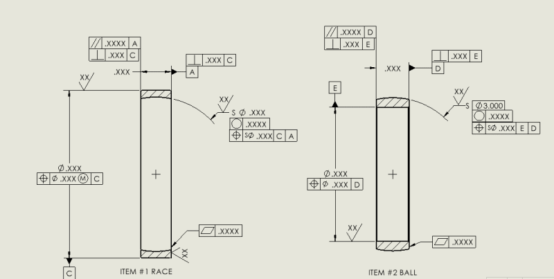
You mean like that? I am using ASME 1994/2009 version, I know concentricity is removed from 2018 version, but many bearing standards has concentricity on the race OD. We do have CMM in house too.
I am lost, I am not sure which is more correct, concentricity and the TP both controls the location of the spherical surface, I guess the only difference is just the way the tolerance will be measured? TP might be easier to measure.
 
Neither Position nor Concentricity is "easier" to measure. They often cover similar cases; the ones they don't have been discarded by the 2018 version eliminating concentricity without any explanation of the cases that only concentricity controls.

The difference, in this case, is that concentricity didn't/doesn't appear to cover a combination of multiple datum features to establish a datum axis or datum point.
 
Few people intend what Concentricity meant per the ASME Y14.5 standard when they specify that tolerance. Although Concentricity is not a surface control, it is affected by the form of the feature in a way that position doesn't. While position controls the axis of the inscribed or circumscribed cylinder, Concentricity controls center-points of line segments across the datum axis. If there was a cavity in the hole's or shaft's surface, the Concentricity measurement may be thrown out of tolerance while the position wouldn't. But if there is a matching-opposed cavity across the axis, the Concentricity deviation could be eliminated, unlike in the case of Runout. If it is required to control a combination of location, orientation and form, Runout or Total Runout is often simpler to measure using just basic inspection equipment, although it is a bit more restrictive (it rejects any type of out of roundness regardless if the form deviation is symmetrical or not).
 
Thanks for the explanation, guys, I didn't think of the cavity salutation. So basically, concentricity does control the form if it's not diametrically symmetrical.
Concentricity FCF can have two datums, right? in the above case, with respect to datum E & D.
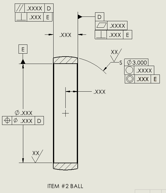
A vendor suggested changing the callouts to something like this below:
Capture5_tvwhn3.png


It has a dimension with tolerance from datum D to the center line, I am assuming this is for concentricity? which is confusing to me, like greenimi suggested earlier, I could make datum D the midplane of the width, this way, I can get rid of the dimension from datum D to the center. Locating the center point with a tolerance in the horizontal direction is kind weird to me, it feels like the tolerance zone became an ellipse. Can someone confirm if it's legal?

Since runout only controls the variation when rotating about the datum axis, runout on a spherical surface sounds difficult, I guess you can do it if it's done with respect to multiple axes to ensure the circularity in all directions.
 
It is unusual to have a concentricity tolerance referencing more than one datum feature, but in your case the reference to E, D would be interpretable, had the dimension from datum feature D to the sphere's center point been basic. It would then mean that the spherical tolerance zone for concentricity is coincident with datum axis E and at a fixed (basic) distance from datum plane D.
 
If you want to keep the ID for the item #2 (BALL) callout as shown, I think, the shown position should be changed to perpendicularity (for datum feature E). Or I think even better to remove the position callout of E to datum feature D, since the relationship between the side faces and the inside diameter ID is already defined by the perpendicularity to E (two callouts) of the side faces.
By the same token, if the size for the shpehre is basic (Ø3.000 basic) then why concentricity is not changed with profile. Therefore, the location of the sphere should be profile|.xxx|E|D|
 
And one more adition
Quite frankly, the original drawing you posted (in the start of this thread) is a better shape (correctness to the ASME standard) then the one you are proposing in your last post.
Not sure why, but this is my perception and consequently my opinion.
I have the right to be wrong and I will stand corrected, if applicable.
 
Status
Not open for further replies.
Back
Top