Eng-Tips is the largest engineering community on the Internet

Intelligent Work Forums for Engineering Professionals

  • Congratulations waross on being selected by the Tek-Tips community for having the most helpful posts in the forums last week. Way to Go!

TP without a basic dimension? 5

Status
Not open for further replies.

rollingcloud

Aerospace
Aug 9, 2022
167
0
0
US
wwwwssfe_epa2l2.png


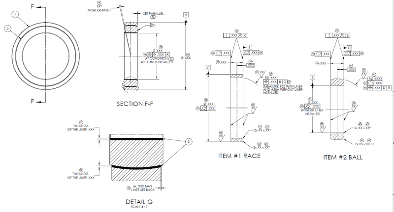
This was done by someone who I cannot reach out and ask. I am trying to make sense of his measurement drawing, it's not easy since I am a noob as well...
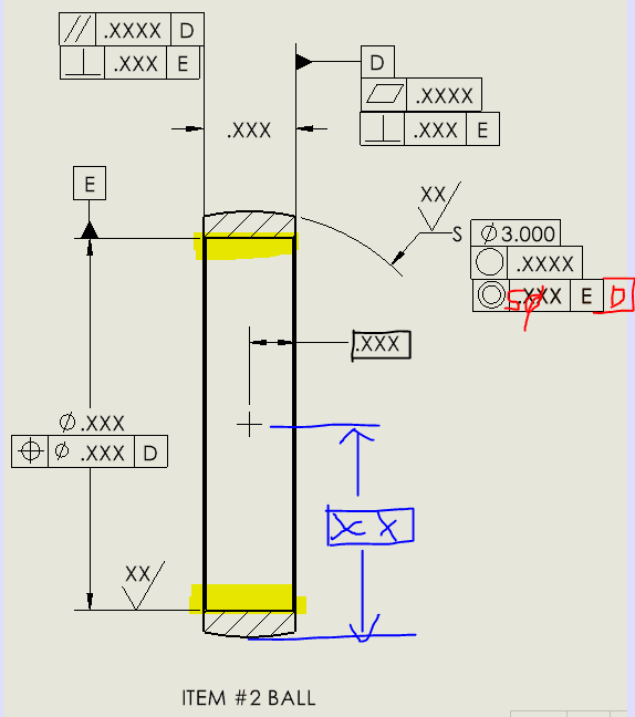
It has 3 axes as datums A, C and E, I am pretty sure that's not correct, one axis (datum C) should be enough IMO.
Also, none of the TP callouts have basic dimension.
Moreover, calling TP on the ball dia does not make sense to me.
Calling two flatness on the race seem to be not needed, especially if both surfaces are controlled by perpendicularity already.
Is form control on the ball OD a good idea?
 
Replies continue below

Recommended for you

My tiny brain got mixed up between the midplane and the center point in the horizontal direction, the center point would be on the midplane only if it's perfectly symmetrical. So if there is no such dimension from datum D to the center point, the spherical surface might turn out to be something like this:
Capture6_gvtmo0.png


I am still trying to process what a profile callout with datums look like in terms of differentiating between the other callouts.... might have to come back to this one later

If the bearing is going to be thermally expanded when assembled with the housing and the ball ID is going to have interference fit with the shaft. I want to make sure the contact stress will be evenly distributed between the mating surfaces. Would concentricity + cylindricity an overkill on the race OD? with respect to datum E when assembled? Not sure what to do on race's ID since there is a liner on it, there is a requirement of radial & axial play, so maybe I don't need to control the race's ID with additional callouts?
 
While I am uncertain as to the basis for claiming to know what other people intend**, that fails to answer about the reasoning the committee used, considering that it was previously stated:

NOTE: Concentricity requirement as described above is substantially different than position, profile, or runout tolerances.

In 2009, it was substantially different and in 2018 it became substantially the same. Why did the committee decide that, after decades of being different, that it was now the same?

Of course, one would have to be on the committee to know that detail and committee members never divulge the reasons.

In addition "(or the median points of correspondingly located elements of two or more radially disposed features)" means that it applies to features that are not a surface of revolution. This is supported by 7.6.1 (c)

(c) Where the relationship between the derived median points of the controlled feature and the datum axis is a primary design concern, or where the coaxial control of noncircular features is a design requirement, concentricity tolerancing is recommended.

**The easy fix is to provide a better explanation. Calculators still come with buttons for functions many users don't understand because, for some users, those functions are critical. Seems like if that is the real reason, which can never be confirmed no matter how one knows what others intend, it seems elitist on the part of the committee, basically stating lowly users are too stupid to understand so they cannot use it any more.
 
3DDave,

I think the OP is looking for a solution (maybe a practical one). Related and adjacent subjects could be discussed, but I am afraid the current conversation ends up in the theoretical weeds and Y14.5's politics. I am sure the OP did not come here for that!
 
I am just learning the basics, but personally I would have kept concentricity for more options.

I missed greenimi's last reply earlier, I believe concentricity is fine in this case, might even be better for spherical contact purpose.
What I am really confused at is the dimension from datum D to the center (call it character 1), it was not basic, but I think it should be basic, I am trying to think of a reason why its not basic, I might have to ask the vendor about this...
 
If this is reference from the last (unidentified in 20 Jan 23 15:27 post) vendor drawing, it's from the surface that is also identified as datum feature D because there is no width dimension to create a feature of size from which a midplane could be constructed. It is not from datum D. It's not basic because it doesn't have to be basic. No feature control frame for the spherical surface refers to the datum feature D.
 
Practically, there are a large number of bearing manufacturers in Connecticut. If rollingcloud's location info is correct they are likely to be able to visit any of them in a one-day round trip. If the problem is reverse engineering from one supplier to become or contract with another supplier, that's more difficult as without an end item engineering goal it's not possible to make sensible decisions.

The cleanest solution is specifying the running surfaces with sphericity via circularity geometric tolerance to 5 microinches or less, a size variation of 100 microinches or less. Larger limits can be used - expect it to feel lumpy when it's turned and to wear unevenly.

Use the spherical surface as the primary datum feature for a position geometric tolerance on the cylindrical surface and a position geometric tolerance with the sphere as the primary datum feature and the cylindrical feature as a secondary datum feature for the width of the two faces.

Alternate: Use a position geometric tolerance on the width of the bearing with the sphere surface as the primary datum feature and use a position geometric tolerance on the cylindrical surface with the sphere as the primary datum feature and the width as the secondary datum feature.

Add in a total runout or a perpendicularity geometric tolerance between the faces and cylindrical surface for better refinement and a cylindricity geometric tolerance to the cylindrical surface as a refinement for that.

There is no need for assembly tolerances except as marketing material.

The original drawing is what is made for a manufacturing process drawing rather than a functional description of how the parts interface with each other.

Problem solved, unless the more complicated and less functional manufacturing process step system is wanted.

 
Yes, the vendor one. Ok, I got mixed up between TP & concentricity, I was initially trying to find the center point of the concentricity tolerance zone, I just realized that concentricity tolerance zone of a spherical surface is automatically a sphere, it does not need any basic dimensions like TP. Concentricity with respect to datum E basically compares it's derived median points to the spherical tolerance zone centered on datum E.

I need to have basic dimension to locate the location of the hole right? Or using symmetry on the secondary datum? What is the purpose of using TP on the width?
 
rollingcloud said:
Concentricity with respect to datum E basically compares it's derived median points to the spherical tolerance zone centered on datum E.

And without additional constraints this tolerance zone can float relative to the part freely right and left along the datum E axis, allowing approval of a spherical shape as you posted on 20 Jan 23 21:43. You do have an additional, separate requirement for location, but that directly toleranced (+/-) location of the sphere's center is ambiguous about how the center point should be derived.
 
Burunduk,
I agree with what you said so far, but I am a little bit confused (due to the structure of the thread) on which scheme are you proposing? Could you please clarify (in words or sketch)
 
greenimi, I am talking specifically about the concentricity tolerance in the last version of rollingcloud's ball component detail, which he posted above at 20 Jan 23 15:27. I am addressing this in the context of the questions he asked about referencing a secondary datum feature and whether the dimension locating the sphere's center should be basic or not. That figure has a number of other issues as well, most of which I think you addressed at 20 Jan 23 18:50.
 
Burunduk,
So do you agree that the first drawing posted (opening of this discussion) looks better than the subsequent revisions? (I am not saying it is flawless)
 
greenimi,
Yes, I agree that the original drawing looks better overall, despite some flaws.
And as far as the spherical feature is concerned, the combo of positional tolerance for location and surface profile for size and form seems a reasonable choice, and preferable over the latest combo of concentricity, circularity, and the uncontrolled basic size dimension.
 
For the same |concentricity|XXX|E|so the allowable tolerance zone for that concentricity is still a cylindrical zone, the derived median points of the spherical surface is a spherical zone. That dimension to the center, how can we be sure it can be used for the concentricity callout when it's not part of the FCF? If it was a basic dim, maybe then I can assume it's intended for the concentricity callout?
Maybe somehow a secondardary datum (plane/point) defined on that center point and be used for the concentricity would be more clear? (if we must stick with concentricity)

For the original drawing in the beginning, how does the true location of the hole gets locked down? Is it controlled by the TP on assembly level?
The profile callout without datum, is just controlling the shape/form of the surface right? it alone can prevent the spherical surface being slanted?:
Capture6_gvtmo0_hm84ca.png

I understand that you can also prevent it by defining the dimension from datum D to the center of sphere.
 
rollingcloud,
Currently, the shape of the concentricity tolerance zone in your figure is undefined. A concentricity tolerance zone can be cylindrical or spherical. A diameter symbol (⌀) preceding the tolerance value would indicate that it is cylindrical, but it is uncommon to define a cylindrical zone for the center point of the sphere. To indicate a spherical zone, the spherical diameter symbol (S⌀) has to precede the tolerance value. It is only possible to define the location of a true center point/plane/axis/ or true profile and the corresponding tolerance zone relative to datums by basic dimensions, and doing so is only meaningful if the corresponding datum features are referenced in the geometric tolerance that governs this location.
 
So to fix the previous concentricity callout, it would be something like this?:
Capture_tcrxlv.png

Based on paragraph 1.4(k) of the 2009 edition, we can assume the hole is coaxial with the spherical surface, hence datum E is going to be centered automatically, so the blue dimension is extra and should be deleted, correct?
 
rollingcloud,
Yes, this would locate a spherical tolerance zone in the datum reference frame, coincident with datum axis E and at an exact distance of .xxx from datum D. In that tolerance zone, the median points of the sphere controlled by concentricity will be evaluated. You are correct that centering is implied and the blue dimension is redundant.

The size of the sphere, ⌀3.000 basic, is uncontrolled.

I find the original scheme with the datumless profile and position with ref. to D and E better.
 
Thank you for the correction.
I just noticed that in solidworks, spherical diameter symbol is not allowed in concentricity FCF.
Capture7_hy1mx9.png


On the original drawing, the tolerance zone created by the basic sphere diameter (red), profile (blue) and TP (green zone) is like the following?
Capture8_slzkad.png
 
rollingcloud,

OP said:
just noticed that in solidworks, spherical diameter symbol is not allowed in concentricity FCF.
I agree with you and other CAD packages have the same limitations.
In ProE I can add manually SØ (even the S symbol is not pickable)


I haven't been following the entire thread so forgive me these questions:

1. Why is concentricity used in the first place? What design intent requirements lead to the desire to specify it?

2. Assuming it's really needed from the functional point of view, I am not sure Y14.5 provides an interpretation for it in cases where the toleranced feature is spherical but the datum feature is different than a sphere.
 
Status
Not open for further replies.
Back
Top