Continue to Site

Eng-Tips is the largest engineering community on the Internet

Intelligent Work Forums for Engineering Professionals

  • Congratulations KootK on being selected by the Eng-Tips community for having the most helpful posts in the forums last week. Way to Go!

TP without a basic dimension? 5

Status
Not open for further replies.

rollingcloud

Aerospace
Aug 9, 2022
172
wwwwssfe_epa2l2.png


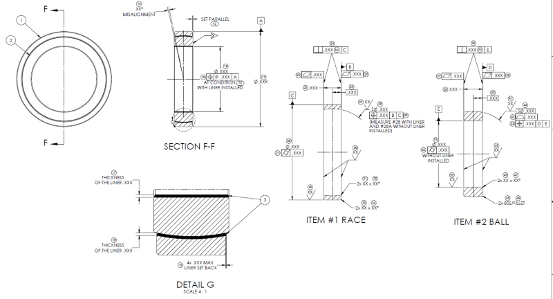
This was done by someone who I cannot reach out and ask. I am trying to make sense of his measurement drawing, it's not easy since I am a noob as well...
It has 3 axes as datums A, C and E, I am pretty sure that's not correct, one axis (datum C) should be enough IMO.
Also, none of the TP callouts have basic dimension.
Moreover, calling TP on the ball dia does not make sense to me.
Calling two flatness on the race seem to be not needed, especially if both surfaces are controlled by perpendicularity already.
Is form control on the ball OD a good idea?
 
Replies continue below

Recommended for you

pmarc,

pmarc said:
Why is concentricity used in the first place?

Sorry to jump into this conversation, but concentricity is not used in the "first place". It is used in the "second place" [wink]
On the initial drawing (shown at the begining of this thread) position is depicted.
 
There should be a chart showing how different combinations of datum feature references resolve to datums. If an axis and a plane are used in the datum reference frame that resolves to a datum point, a datum axis, a datum plane, and two perpendicular, but rotationally unconstrained planes passing through the axis.
 
There is a chance that such a chart (or similar) will be shown in the next version of the math standard, Y14.5.1.

Per that chart, a cylindrical feature primary and a planar feature secondary will resolve in so called revolute invariance class which will be associated with a datum axis and a datum point lying on that axis (the point will be located at the intersection of the primary axis E and the secondary plane D) - similar to the scenario of a conical feature defined as primary datum feature.

So, in my opinion, this will still not make the application of the concentricity tolerance, as shown in the latest sketch, valid as the nominal center of the toleranced sphere will not be concentric with the datum point. Unless one finds a way to specify that the concentricity error is to be evaluated relative to a point that is offset by a basic distance from the datum point.

The situation would become interesting, though, if D in the example was a center plane established from the width of the part.

As far as the number of planes of the DRF is considered, I would say that both cases above should resolve in 3 mutually perpendicular planes, two of which would be allowed to freely rotate about an axis passing through the two planes. Similar to what is shown in fig. 7-55 in Y14.5-2018 or fig. 4-44 in 2009.
 
"revolute invariance class"? Even Google struggles with that.

All that is necessary is to locate the center. If that is done, that is sufficient.
 
To locate the center, one doesn't need Concentricity and all the ugliness that goes with it. Position should be well enough.
 
The center isn't found by concentricity - the center is found by evaluating the DRF and the basic dimensions.

Not sure there is a difference in ugliness. What I see for position is putting on a mathematical blindfold and finding the solution to some adjacent problem that should be nearly as difficult if not for simplifying assumptions.

To know more I'd just need to see the proceedings that the committee generated as a basis - a white paper describing the reasons and investigated proposed solutions and why the one(s) chosen are the best fit.
 
I am not sure what we are discussing here. If it's the establishment of the DRF, then it absolutely doesn't matter if we are talking about Position or Concentricity. The DRF needs to be established identically in both cases.

The points I am trying to make making are: (1) that I doubt there is a design need to apply Concentricity in this particular case and (2) that the concentricity tolerance relative to a DRF established from a cylindrical surface and (most of all) from a plane that doesn't nominally pass through the center of the toleranced sphere doesn't seem to have a solid mathematical definition in Y14.5. To me, it's kind of like specifying a concentricity tolerance on a cylindrical feature relative to a cylindrical datum feature that isn't nominally coaxial with the toleranced cylinder.
 
greenimi,
I am able to manually add it as well, but it was kind odd that they all have the same limitation...

pmarc,
Concentricity was brought up by the vendor, I have been trying to understand the basics and to determine if the way concentricity was used is even correct/legal first before I reach out and ask. I am not sure what was the reason behind it, I am guessing it's their convection or could simply be a mistake. Bearing standards use concentricity on the race OD with respect to datum E ( to ensure spherical contact?) But I agree that on the component level, concentricity seems to be worse than TP and profile.

The way I understand it is that you are saying datum E and the basic dimension from datum D to the center (forms centerline) won't form the center point of the spherical tolerance zone of the concentricity because they won't necessary intersect? If so, then when using TP, it would have the same problem right? So to fix it, we can use the spherical surface as the datum feature as suggested previously by 3DDave? Or we can add datum F as a midplane while keeping the basic dimension from datum D. That way, datum E is ensured to intersect with the plane.
 
Is the true position of a hole aligned to the DRF or can it be offset from the DRF?

If one says - is this surface concentric to that surface - that's one proposition. But the standard asks "is this feature concentric to that datum?" or, as a practical matter, to that datum feature simulator or true geometric counterpart.

Not to the origin of a DRF.

Of course that leads to the question, can the tolerance zone (point/axis) be shifted away from the datum feature's axis? It can for position and profile geometric tolerances. If a theoretical axis or point can be unambiguously determined for those cases, can't it be used as a reference for other location cases?
 
rollingcloud,

Concentricity was brought up by the vendor, I have been trying to understand the basics and to determine if the way concentricity was used is even correct/legal first before I reach out and ask. I am not sure what was the reason behind it, I am guessing it's their convection or could simply be a mistake. Bearing standards use concentricity on the race OD with respect to datum E ( to ensure spherical contact?)
I would highly recommend asking the vendor how they understand the concentricity requirement without even first trying to determine on your own if what they are proposing is legal or not. As was already brought up in this thread, there are cases (way too many of them) when this geometric characteristic is misunderstood and therefore misapplied.


The way I understand it is that you are saying datum E and the basic dimension from datum D to the center (forms centerline) won't form the center point of the spherical tolerance zone of the concentricity because they won't necessary intersect? If so, then when using TP, it would have the same problem right?
The problem with Concentricity, unlike with Position, is that by definition it requires all median points of the spherical surface to be congruent with a datum center point. Firstly, I don't think that the datum center point in this context was ever envisioned as a point of intersection of the primary datum axis and the secondary datum plane or center plane; it was rather thought to be a center point established from a regular spherical datum feature. Secondly, since the true location of the center of the sphere is in your case offset from that point of intersection, I don't think you would want the spherical surface's median points to be congruent with that point.

For Position all you care about is that the center point of the Actual Mating Envelope of the spherical surface (which for an external surface is the smallest perfect spherical envelope circumscribed about the actual surface) is within the position tolerance zone. But in this case the tolerance zone can be located anywhere relative to the datums used to establish the DRF - either at the datums or totally offset from them.


So to fix it, we can use the spherical surface as the datum feature as suggested previously by 3DDave?
While from the functional point of view, this would most likely be the right choice, it would fix the problem to some extent only. You would still need to find a way to control the same type/nature of form error that the originally applied concentricity tolerance was able to control, namely the "symmetry" of the distribution of the form error relative to a datum, assuming you trully cared about it. If you didn't, then that would just be another argument for not using Concentricity at all.


Or we can add datum F as a midplane while keeping the basic dimension from datum D. That way, datum E is ensured to intersect with the plane.
(1) If you made the width a datum feature F, the basic dimension from D to the center of the sphere would not be needed. The implied basic 0 linear dimension would then apply just like it applies now for the distance between the sphere center point and the datum axis E.
(2) As I tried to imply in one of my previous replies, this would still be an unusual application of concentricity tolerance due to the fact that the datum for that tolerance would not be a "classic" center point established from a spherical datum feature.
 
Concentricity isn't controlling form error - it controls the location of the form error.

Which is why my solution doesn't use concentricity.
 
3DDave said:
Concentricity isn't controlling form error - it controls the location of the form error.

That's exactly what I meant by saying it controls the >>"symmetry" of the distribution of the form error relative to a datum<<. If you feel your "controls the location of the form error" adds additional value, I am OK with using your term instead.
 
Sorry - I stopped too soon with " You would still need to find a way to control the same type/nature of form error" as I wasn't expecting a shift to an entirely different concept.
 
pmarc,
I certainly am not in favor of the scheme with concentricity, but I find it interpretable (per the 2009 or 1994 versions of the Y14.5 standard).

"7.6.4.1 Concentricity Tolerancing. A concentricity tolerance is a cylindrical (or spherical) tolerance zone whose axis (or center point) coincides with the axis (or center point) of the datum feature(s)"

I see no indication that the center point of the spherical tolerance zone can only coincide with a datum point or the origin of the datum reference frame. Although not common, the center point of the spherical tolerance zone can also be congruent with a datum axis. This is the case in the scheme in which concentricity is used with reference to datum feature E as primary which provides the datum axis, and to datum feature D which provides an additional constraint, while the basic dimension from it defines the exact location of the tolerance zone along the axis and relative to the datum reference frame.

pmarc said:
There is a chance that such a chart (or similar) will be shown in the next version of the math standard, Y14.5.1.

Per that chart, a cylindrical feature primary and a planar feature secondary will resolve in so called revolute invariance class which will be associated with a datum axis and a datum point lying on that axis (the point will be located at the intersection of the primary axis E and the secondary plane D)

I sure hope that such addition will never take place. It is a mistake that will only add confusion to an already commonly misunderstood subject of datums and datum reference frames. A cylindrical datum feature as primary provides a datum axis, and the axis is associated with 2 planes of the datum reference frame. The secondary datum plane is the third plane of the DRF. That is all that's required. There is no need for a datum point. A datum point is not associated with neither the cylindrical nor the planar datum feature. There is no need to establish additional datums from combinations of different datums. The establishment of the 3 orthogonal planes and the axis system of the DRF should be as brief and direct as possible, without redundant steps.
 
Explaining exactly how datums function would eliminate the confusion, but the committee has chosen not to. They keep mixing part features with the idealization of part features, an idealization that is what makes the general notion worthwhile.
 
Be aware that some of my questions might be stupid...
If you are creating the datum point based on the same spherical surface that concentricity is applied to, wouldn't it be self-referencing?

I still don't understand how its ok to offset from the datum for TP but not for concentricity. Both requires the true center point with a tolerance zone around it. The only difference I see is that TP is controlling the deviation of a single measured point (center point of the spherical feature) from the true center point, while concentricity controls the deviation of multiple points (median points of the spherical feature) from the true center.

But the midplane is just the midplane of the width, the spherical center point does not have to lie on the midplane. Unless I can assume that?

A quick question on the datum. Would the accuracy of datum E be an issue since the L/D ratio is so small? I am thinking the primary datum should be the flat surface (datum D), and define datum E as secondary with perpendicularity based on datum D.

Capture5_tvwhn3_gsgyle.png

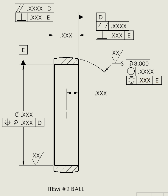
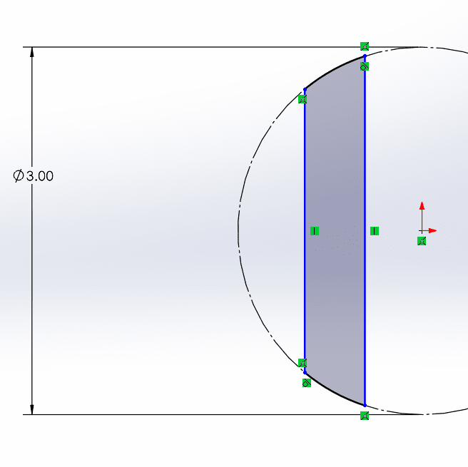
Above is vendor's version, what is the biggest issue with this version besides that size of sphere is not controlled? Technically, even though it's not an ideal drawing, it's actually legal? Since it has a dimension from datum D to the center. It prevents the spherical surface to become the following, right?
Capture6_uyftl7.png
 
Burunduk,
"7.6.4.1 Concentricity Tolerancing. A concentricity tolerance is a cylindrical (or spherical) tolerance zone whose axis (or center point) coincides with the axis (or center point) of the datum feature(s)"

I see no indication that the center point of the spherical tolerance zone can only coincide with a datum point or the origin of the datum reference frame. Although not common, the center point of the spherical tolerance zone can also be congruent with a datum axis.
The problem is not in how the center point of the spherical tolerance zone is located relative to a datum or datums. The problem is in the establishment of the median points for the evaluation of the concentricity error. For a spherical toleranced feature, for everything to make sense, the opposed points from which then a median point will be established, must lie on a line containing the datum center point and on different sides of that point. In the example being discussed here, there is no datum center point to begin with.

I sure hope that such addition will never take place. It is a mistake that will only add confusion to an already commonly misunderstood subject of datums and datum reference frames. A cylindrical datum feature as primary provides a datum axis, and the axis is associated with 2 planes of the datum reference frame. The secondary datum plane is the third plane of the DRF. That is all that's required. There is no need for a datum point. A datum point is not associated with neither the cylindrical nor the planar datum feature. There is no need to establish additional datums from combinations of different datums. The establishment of the 3 orthogonal planes and the axis system of the DRF should be as brief and direct as possible, without redundant steps.
To keep it short, I definitely agree that the datum theory should be as brief and direct as possible, unfortunately it's not that easy to do as some could think, and I know you realize that very well. Don't get me wrong, I am all for simplification but I am afraid that a solid theory on datums/datum systems/datum reference frame will require certain level of complexity.

-----------------
rollingcloud,
If you are creating the datum point based on the same spherical surface that concentricity is applied to, wouldn't it be self-referencing?
This is not what I said, but since you mentioned it, I don't think that controlling concentricity of a spherical feature relative to a datum center point established from that feature is necessarily a self-referencing. I am not saying this is something that should be commonly used (actually, I am pretty sure this would be seen by many people as blasphemy), but per Y14.5 theory it would be interpretable. It would be self-referencing (i.e., would make no sense) if it was a position callout, though.

I still don't understand how its ok to offset from the datum for TP but not for concentricity. Both requires the true center point with a tolerance zone around it. The only difference I see is that TP is controlling the deviation of a single measured point (center point of the spherical feature) from the true center point, while concentricity controls the deviation of multiple points (median points of the spherical feature) from the true center.
Concentricity doesn't control deviation from the true center of the spherical feature. It controls deviation from the datum center point and most of all, as I already try to explain to Burunduk, the datum center point is involved in the procedure of establishing the median points. So first, there needs to be a datum center point (which is not the case on your drawing). Second, that datum center point would need to be contained within the toleranced spherical feature (in nominal condition, it would have to be concentric with the center of the feature).

Above is vendor's version, what is the biggest issue with this version besides that size of sphere is not controlled? Technically, even though it's not an ideal drawing, it's actually legal? Since it has a dimension from datum D to the center. It prevents the spherical surface to become the following, right?
Well, the fact that the size of the sphere is not properly controlled may actually be a first indicator that the vendor doesn't really understand what they have put on the drawing. Also, ignoring for a moment the whole conversation about the correctness of application of concentricity, the lack of secondary datum feature reference in that feature control frame does not prevent the spherical surface to become as you shown in your sketch. I assume the horizontal .XXX dimension from the surface D to the center of the sphere is there to prevent this unwanted shape to happen, but since it is not shown as basic, there is not even a standard interpretation for it. An additional element that looks strange, at least to me, is that the hole E is controlled for perpendicularity relative to D (by incorrectly using the positon symbol) and at the same time the surface D is controlled for perpendicularity relative to E. In summary, these are all sufficient signals, again at least to me, to check if the vendor really understands concentricity tolerance.
 
pmarc said:
The problem is not in how the center point of the spherical tolerance zone is located relative to a datum or datums. The problem is in the establishment of the median points for the evaluation of the concentricity error. For a spherical toleranced feature, for everything to make sense, the opposed points from which then a median point will be established, must lie on a line containing the datum center point and on different sides of that point. In the example being discussed here, there is no datum center point to begin with.

I can only see how for everything to make sense, the opposed points from which then median points for a spherical feature will be established, must lie on a line containing the center point of the spherical tolerance zone and on different sides of that point. The center point of the tolerance zone is perfectly concentric to something - and that something is either a datum point, or a datum axis. If the only reference is a datum axis, then as usual for underconstrained requirements, a fitting procedure can be performed for the location of the tolerance zone along that axis depending on how the actual feature was produced. If a secondary datum reference is used to lock the axial translation, no fitting is relevant, as the tolerance zone and the part are mutually constrained. You say that a spherical tolerance zone for concentricity can only be constrained to a datum point, but I see no indication for it in the standard, at least not in Y14.5. So I think it IS about
how the center point of the spherical tolerance zone is located relative to a datum or datums after all.

Here is another relevant quote:
"7.6.4 Concentricity
Concentricity is that condition where the median points of all diametrically opposed elements of a surface of revolution (or the median points of correspondingly located elements of two or more radially disposed features) are congruent with a datum axis (or center point)."


Why can't a sphere be concentric to an axis?

I agree that solid theory on datums/datum systems/datum reference frame will require certain level of complexity, but that doesn't justify adding redundancy. If a datum axis and a datum plane derived from the primary and secondary datum features, they are enough for DRF establishment and there is no reason to introduce an additional datum point which is not derived from any specific datum feature. The intersection between the datums is the origin of the DRF, not a datum point.
 
"7.6.4 Concentricity
Concentricity is that condition where the median points of all diametrically opposed elements of a surface of revolution (or the median points of correspondingly located elements of two or more radially disposed features) are congruent with a datum axis (or center point)."


"7.6.4.1 Concentricity Tolerancing. A concentricity tolerance is a cylindrical (or spherical) tolerance zone whose axis (or center point) coincides with the axis (or center point) of the datum feature(s)"

I made some portions of the two quotes you provided bold and the reason for this is that I believe the intent of the statements has always been to consider concentricity of a spherical feature relative to a datum center point established from another spherical feature.

The datum center point mentioned in both quoted paragraphs doesn't exist on the drawing and on its different variations that are being discussed here, so this is where everything fails. Unless the concept of a point on a line located at the intersection of datum axis E and datum center plane D is introduced.

Of course we could explore some other options, such as for example that the median points of the spherical feature are found at the section planes perpendicular to the datum axis, but then in my mind this would question the need for a spherical tolerance zone and in general would be another stretch.
 
Ah - the old problem of lack of imagination from the committee strikes again. There's no datum feature coincidence required for position or profile, but there is for concentricity. Even though the point in question is still a point regardless of how the point was determined and the committee decided that there is no difference between concentricity and position, for some unexplained cases, after explaining they are entirely different for others, which they did explain.

It's like a CAD system that requires one to MOVE lines but TRANSLATE arcs. CAD software writers are smarter than to do that but committees aren't. Three ways to control where a surface is and one of them is left out from references enjoyed by the other two.

 
Status
Not open for further replies.

Part and Inventory Search

Sponsor