Continue to Site

Eng-Tips is the largest engineering community on the Internet

Intelligent Work Forums for Engineering Professionals

  • Congratulations SSS148 on being selected by the Eng-Tips community for having the most helpful posts in the forums last week. Way to Go!

Transfer Slab Modeling 1

Status
Not open for further replies.

StayHome

Structural
Mar 30, 2020
8
Hi guys hope you all safe during this hard time.
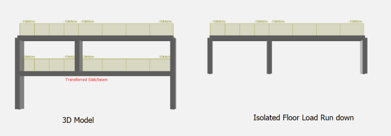
I have a structure that contains many levels of transfer slab and I am looking for a convenient way to build the model in FEA package, say Ram Concept.
This is what I am doing now
Analyse and design the slab based on floor by floor load run down procedure - model the top level and get the reactions and then model the lower level and input the reaction from top level as loading applied on the slab and then another lower level till the lowest floor.
Q1, Is this the correct procedure?
Q2, If the answer to Q1 is no, what is your procedure?
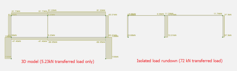
Q3, If the answer to Q1 is yes, what can I do to quickly input the reaction from upper floor as loads on the floor in say, Ram Concept? Is there any way to automatically get the reactions and transfer to the loads instead of manually input? I am thinking of using Ram Structural System and then export slab by slab but the problem I found is the loading from a full model is not the same as floor by floor load rundown and thus cannot be used in slab analysis and design.(Can be used for envelop purpose though). Am I wrong?

Thank you.
 
Replies continue below

Recommended for you

SerbGile,

20% is only an estimate, it may be between 5%-20%, all depending on your spans.

Ever had a really short end span and the edge column go into tension? This is the same effect, ie the distribution is based upon the elastic stiffness of the floor structure.

 
I still don't get where you get this 20% from. Looks like you are talking about something like moment redistribution? The problem here is in regards to the transferred loads. In isolated floor, pin restraints are assigned to transferred members and thus more loads go to them while in reality it should be springs instead of pin supports and thus attract less loads depending on the stiffness of the spring and, how stiff the springs are depends on the stiffness of the transferred slabs below, which is why 20% doesn't make much sense to me. It can be way greater 20% in isolated floors than in 3D models. Can you elaborate the theory behind this 20% increase in axial force?
 
i have considered this question and dealt with consequences of it a number of times... option 2 by trenno is my preferred approach with the reasoning given by RAPT of construction sequence and do you trust the 3d results being the prime reasons.

I have have seen problems in 3D models of vierendeel action, of columns and many typical floors above, transferring loads away from a transfer. Also the sensitivities of the columns and slabs stiffness overall making it very subjective to engineering judgement. My view is that models should be used to verify and check an intended design approach and load paths, i find that there can a reliance upon 3d models to make some decisions based on analysis that should actually come from engineers.

I dont consider transfers as being something to skimp on.

To answer how to take reactions from ram concept model and apply them to another, i can't answer that from one Ram Concept model to another. But but i recently have transferred loads from a Robot analysis to a ram model via excel / text files. It didn't take too long to set up - I expect from Ram to Ram should be easier and faster. The primary check i recall was making sure the reaction node numbers got correctly mapped to the right positions in ram, and found this was best done visually. From memory ram requires point loads to be input via x,y,z coords and not via a node number.
 
SerbGile,

As I said previously, the 20% is not a hard and fast figure. It's an upperbound estimate, see the link below and in particular the reaction coefficients for further details. As I also said previously, this method will result in conservative transfer loads.

The correct value for a spring support to account for the transfer below is so difficult to get right, I'd rather have slightly higher loads on the transfer and sleep well at night.

Continuous Beam Formulae


Trenno, Looks like you are talking about the difference between tributary area method with FEA and 20% is due to beam/slab continuity.
However, I think the main concern of this thread is regarding the transferred loads between full model and traditional load rundown (isolated model floor by floor). Below is the example that shows the huge difference between the transferred loads, (5+8m span with 10kN/m line load, section 400X1000). Using the later method will return a way to conservative transferred loads as the transferred slab is nowhere near a support but a spring. Put construction sequence aside, will you guys use the loads from the full model to design transferred slabs/beams? (I think enveloping these two method is not possible as the results differs greatly, not even close in most cases.
t1_h1h8u1.png

2_ttvpps.png
 
Don't forget to state your stiffness modifiers on the For Construction drawings so the contractor can install them!

 
I honestly don't think you get the concern here. check the link provided by retired13 above. That example explains the main concern when it comes to transfer slab design. And there is no such a 20% sort of thing. We are talking about evaluating transferred loads not just comparing tributary area method with FEA for a normal slab due to the slab continuity.
 
The concern is designing a transfer structure.

As I originally stated, there are three main ways of determining the transfer loads and as an engineer you need to make a judgement on what you think is most appropriate for your situation. I like to evaluate transfer loads based upon all three, but mainly method 2, to know where my transfer design sits within these upper and lower bounds.

You originally questioned the elastic load distribution %'s for columns in my method 2, so I explained the reasoning behind it.

This may all be a big miscommunication. Transfers are critical elements, you need to look at them from every which way and satisfy yourself you have all bases covered. It's as simple as that.

 
Trenno, I get your reasoning behind the 20% in your method 2, but that was compared to tributary area method when evaluating the loads to each support. But the topic here is not regarding that. It is regarding whether getting the transferred loads from a full model where transfer slabs are included or from a isolated model where only upper structure are included while transfer slabs are excluded. And the difference between these two methods can be way beyond 20% and depends on the transfer slab stiffness.
 
My process seems a bit different than the ones posted here already, though after the discussion I may take a different approach.

I will typically look to limit the differential "settlement" between the transfer column and surrounding columns to be similar to what we get reported by the geotechnical engineer for the foundations. Using this "settlement" as the allowable long term deflection for the member supporting the column it's relatively easy to back into a spring value to use for the support in the isolated floor model. Doing it this way I've been able to get within about 5-8% difference between isolated floor models vs a full building model. In the isolated floor model, assume we are talking programs like RAM Concept or CSI SAFE for doing the actual slab design, I think having the transfer column sitting on a true pin doesn't necessarily give you a conservative slab response.

After reading everyone else approaches though I will probably start looking into a mixture of what I do along with enveloping the other methods, don't like to try and sharpen the pencil on transfer elements.

My Personal Open Source Structural Applications:

Open Source Structural GitHub Group:
 
Status
Not open for further replies.

Part and Inventory Search

Sponsor