Continue to Site

Eng-Tips is the largest engineering community on the Internet

Intelligent Work Forums for Engineering Professionals

  • Congratulations KootK on being selected by the Eng-Tips community for having the most helpful posts in the forums last week. Way to Go!

Transfer Slab Shear Checks 1

Status
Not open for further replies.

Slurgi

Structural
Jul 16, 2020
7
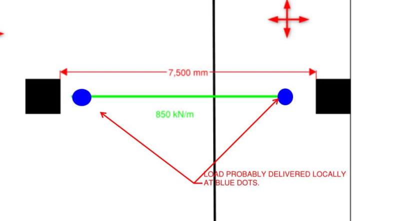
Please review the attached sketch.

I am curious to see what others would do to check shear in a situation like this:
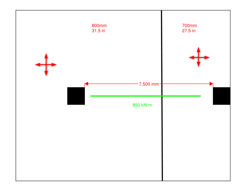
2021-04-09_12h42_37_dlxfov.png


I would think that one-way shear would also be quite critical but cannot find any guidance on what effective width of slab to consider.

Thank you in advance.
 
Replies continue below

Recommended for you

Where is the transfer column?

If you hit the search button on this site, I believe this topic has been discussed a few times previously.
 
No transfer column.

It's a wall transferring along the green line.
 
Unless your slab is very stiff, or endowed with intermittent soft joints, the wall will probably wind up being the spanning element over most of the slab span.

The one way shear question is an interesting one. This NEHRP doc offers some guidance on that in the context of raft foundations.

c02_ktgt0z.jpg
 
What kind of wall is it? RC in-situ wall? Segmented precast? Reinforced CMU blockwork?

What's the distance between each end of the wall and the adjacent column?

As a side note... the more detail you offer in the original post, the better answers will be coming back. The original post is incredibly vague.
 
Thanks KootK; interesting read, will review over the weekend.

First post, will try to give more detail in the future. All RC concrete.

This is happening at a few places; distance to wall is between 250mm and 2m.
 
No worries, Slurgi - most engineers on these forums want to give useful answers and it's hard to sometimes with limited info.

I agree with KootK - as you have a 700mm/800mm thick transfer slab, walls that terminate within around 500mm distance to the column face will mean the majority of the wall load will be dumped within 'd' from the face of the column. Most national codes will give you a one-way shear enhancement benefit in this case. Essentially the load tends to strut itself into the support. See Eurocode shear enhancement provisions below.

When the wall stops greater than say 500mm from the column face, then you could think of a "hidden" beam within the two way slab equal to the lesser of the width of the column slab strip or say column width + 600mm (effective depth 'd') either side. Then you could apply the one-way shear provisions and design beam links as required.

Shear_Enhancement_op4jru.jpg
 
Trenno, it is the width of this hidden beam that I am most interested in.
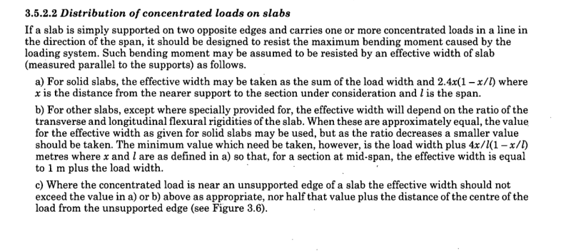
I am unsure about whether taking the column strip would be unconservative. For bending I am taking a much smaller thickness, based on this (found in BS8110):
2021-04-09_16h42_55_slfdsw.png

And taking x at the middle of the wall.
 
What is the thickness of the wall? What is the wall height? How many floors is this wall supporting?

I would say the wall will span between each end if it's tall enough. Assume the wall reaction onto the transfer slab acts over a length of 4 * wall thickness. This "hidden" column base within the end of the wall will be your new concentrated load location. You could then use your british code width equation with "x" being the distance from the centre of the "hidden" wall end column to the centre of the support column below.
 
200mm thk wall; 3m; 10 levels
The "hidden" column approach is interesting.
What I am conscious of taking an overly narrow depth leading to an overkill of shear reinforcement.
Though probably the same can be said for going too wide and providing too little.
 
Engineering judgement comes into play here. It seems you're not too far off an answer.

Say your shear load is around 7m x 850 kN/m / 2 = 3000 kN. Let's say 3MPa one-way shear is the upper limit, then you're looking at width of around for 1500mm for the 700mm deep slab. This isn't accounting for shear enhancement. The shear links required for this indicative situation aren't unexpected and would appear reasonable.


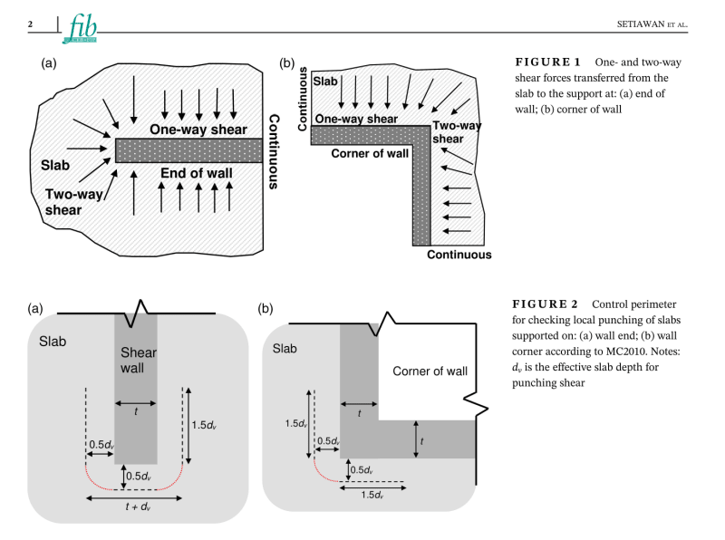
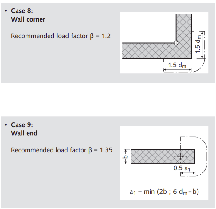
I think you need to check punching shear at the wall-ends with critical perimeter as shown below..

The clip below is for slabs supported on wall, but I think it is applicable for slab supporting a wall. You case is just upside-down.

The need to check punching shear around the columns is obvious.

image_2021-04-12_211055_pojvol.png
 
KootK said:
Unless your slab is very stiff, or endowed with intermittent soft joints, the wall will probably wind up being the spanning element over most of the slab span.

Yes. This is what happened at Opal tower in Sydney. There were bearing failures at the wall ends (which sat on columns) and then some punching failures at the blue dots as the wall settled. Good times :)
 
I dont believe oneway shear would be critical. The whole width of the slab has to shear for oneway shear failure (highly unlikely for most floors).

I would check it for punching shear considering the wall as a whole and local failures. Remember that loads travel on the shortest path, so if you wall is highly loaded at the edges, then loads would concentrate there before it goes to the column.

For the transfer slab, assuming its quite thick, I would consider designing it using strut and tie.
 
Tomfh, shouldn't you expect bearing or punching problems, not both? That is, bearing problems if you assumed distributed support, or punching if you assumed concentrated support at the columns.
 
steveh49 said:
Tomfh, shouldn't you expect bearing or punching problems, not both?

If the wall fails in bearing at the columns the load can start going through the slab instead, which can punch/shear.
 
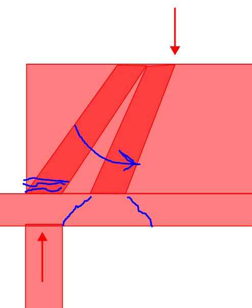
That's interesting Tomfh. This is kind of what I'm imagining. Although it's probably less a case of the strut migrating but, rather, expanding to achieve sufficient bearing width until a bunch of the load has to transfer over via punching shear rather than direct strut delivery.

C01_fxris7.jpg
 
Tomfh said:
If the wall fails in bearing at the columns the load can start going through the slab instead, which can punch/shear.

I'm picturing that they assumed the load/reaction was along the wall length so would have designed for punching shear. The bearing failure was a stiffer but unconsidered path, otherwise they would have provided adequate bearing. So, one or the other unless something else is at play.
 
steveh49,

I would assume they treated the wall as a beam carrying the full load to the support and would not even have considered punching shear. And as a deep beam they had to consider the compression strut coming through the wall onto the column below.

Slurgi,

Send it back to the architect and tell him/her it does not work and the walls need to extend at least to the far face of the columns below! Then make sure you check bearing.
 
Thank you all, great responses.

Re punching shear, here is a guidance based on EC2, which is very similar to what hetgen showed:
1_pak1op.png
 
Status
Not open for further replies.

Part and Inventory Search

Sponsor