Eng-Tips is the largest engineering community on the Internet

Intelligent Work Forums for Engineering Professionals

transformer phase shift - how to measure with oscilloscope 3

Status
Not open for further replies.

MRSSPOCK

Mechanical
Aug 29, 2010
303
0
0
GB
I know this might seem like a schoolboy level question, but I'm afraid I'm stuck.

If I have an unknown transformer and what to determine if there is a phase shift, how can I do it with my two channel scope, considering both channels use the common ground, and so by connecting two channels I am really creating a direct physical connection between the two otherwise isolated primary and secondary coils.

Thanks

I think I am going to be embarassed by the simple answer.
 
Replies continue below

Recommended for you

Are you trying to prove relative phase, i.e. 0° or 180° phase primary to secondary, or actual phase shift due to the transformer? The former is fairly straightforward, the latter is more demanding on your instruments and the answer, when/if you get one, isn't a constant.
 
Connect one end of the primary winding to one end of the secondary winding.
Energize one winding, either one. The voltage may be equal to or less than rated voltage.
Measure the voltage across the primary.
Compare that to the voltage across the free ends of both windings.
If the voltage across the free ends is more than the voltage across the primary the windings are 180 degrees out of phase relative to the common connection.
If the voltage across the free ends is less than the voltage across the primary the windings are in phase relative to the common connection.
You can use the scope to measure the voltages, but I would use a voltmeter.
Or you can use the two channels to compare the waveforms.
OP said:
so by connecting two channels I am really creating a direct physical connection between the two otherwise isolated primary and secondary coils.
Create the physical connection before you connect the scope.

Bill
--------------------
"Why not the best?"
Jimmy Carter
 
So, just to follow up on this subject.

I have two further questions.

I have got hold of a toroid from my supply of scrap.

It has 14 turns on the primary, and 14 turns on the secondary.

They are wound, one LH and the other RH, so the input and output are in phase.

1. So my first question is, what is this arrangement called?

Is it simply an isolation transformer, or does it do some filtering also, or a bit of both?


2. After doing some unwinding / rewinding / phase measurements with this toroid, my second question is this.

If I have transformer in which I wound one winding in reverse by mistake, is it simply a case of swapping the terminals on the output or input stage, to get the thing back into the correct phase? This is only hypothetical, and I realise some tappings which are not true centre tappings would get all messed up by simply swapping terminals. But in an example such as this toroid detailed above, can I simply swap the output terminals, as opposed to unwinding / rewinding it in reverse? Is there something I am unaware of that means I can't simply swap the terminals?

Thanks
 
1) If the windings are not touching each other electrically then it's an isolation transformer.

2) Yes, you can just reverse the connections. You should note that many transformers and transformer symbols sport dots.


The dots are the wires that will have the same phase polarity. Rising waveform on primary dot results in the same rising waveform on the secondary.

xfrmer_dots_prumcv.png


The dots denote the phasing between the windings. About half the time you could care less as it just doesn't matter but other times it's critical and a complete disaster will befall the transformer, the circuit, the function, safety, and sometimes the people standing nearby.

I was told about a very large PG&E transmission transformer in a substation by a guy present when the new transformer was energized for the first time. It was explained to me that the 100+MVA transformer was energized, made a horrible groaning sound that sent everyone fleeing and promptly blew up, he actually said, "lifted inches off the pad". He said it turned out to be a manufacturing defect that had the DOT on the wrong terminal. I believe now days they actually don't trust this and test the transformers before closing switches.

Keith Cress
kcress -
 
Thanks for that. I am planning on making a DC DC converter, so I know it is critical in this case to get the dots right. I'm just playing with some scrap at the minute to understand it better. I'm only working with 12V and a few milliamps on the primary, so I don't think I'll blow myself up :) not yet anyway. Thanks
 
OP said:
...with my two channel scope, considering both channels use the common ground, and so by connecting two channels I am really creating a direct physical connection between the two otherwise isolated primary and secondary coils.

Assuming that the transformer is essentially sitting on a bench (otherwise isolated from any grounding), then there's no issue with applying a common ground (i.e. your grounded input signal source and your grounded 2-channel scope) to simply and directly compare the phasing. Your 2-channel scope would show the two waveforms, either in-phase or out-of-phase. If out-of-phase, then swap the secondary leads (and then recheck if you wish). Perfectly straightforward.

 
Dear OP, I have been wondering about this thread. It started innocently and, for a mechanical engineer, not so bad. I would probably ask something similar if I was to find out if a transmission reverses rotation or not.

But now, I understand that you are going to make yourself a DC-DC converter with that transformer. And that is a quantum jump. Or a triple quantum jump. With peak. Be prepared to ask many more questions. One that I need to ask is if the core material at all is suited for that? Sounds like ordinary transformer plate to me. Another one is if losses and regulation is important or not? And still one is what frequency do you plan to run it at? There could be more questions asked - like that of leakage inductance, ringing, core saturation, flux symmetry. And still some.

You may find that your first question was the easiest to answer. So, you will learn a lot by doing. But it will take time. Some say learn by burning. And that is not at all unusual. Not even at 12 V.

Gunnar Englund
--------------------------------------
Half full - Half empty? I don't mind. It's what in it that counts.
 
Reversing polarities of a winding:
Some power transformers at higher capacities and voltages may have graduated insulation.
Reversing connections may result in a higher voltage to ground than a part of the winding is insulated for.
If the winding is uniformly insulated there is no issue reversing the connections.
Be aware that the construction of some large, high voltage transformers may be a bad idea.
Also in large transformers there may be issues with the length of leads between the winding ends and the appropriate bushings if the connections are reversed. Longer leads may not have the strength required to withstand the forces of fault currents.
This won't apply to you MRSSPOCK, but others are following this thread also.
What is acceptable for small transformers may not scale up to all very large transformers.

Bill
--------------------
"Why not the best?"
Jimmy Carter
 
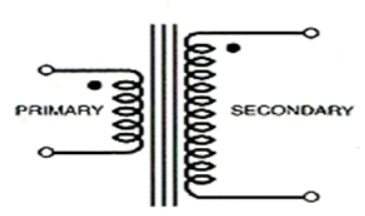
Well, for anyone curious to know what I'm up to, I would like to learn more about transformer design. Even the basics. It seems like a nightmare no matter where I look to learn the theory. I was rummaging through my scrap to see if there was anything I could learn from, as I do actually find that I learn better from burning :) So, I found in my scrap an old strobe light, or timing light, for setting car ignition timing in the olden days. I am planning to reverse engineer it to see what is going on, then try to get my head around the DC to DC conversion part of it, by first learning the basics of how a toroid behaves when I do certain things to it, then do some testing of the existing transformer in the timing light at its operating frequency, (and some other frequencies, etc), then after all that, see if I have learned enough to design something of my own, without simply doing a copy of what I have. It is all academic. I tried for quite a while to understand the theory, but I just always seem to be missing some variables in understanding it all. It seems that fuzzy area is probably the reason why there is simply no on line design program that lets you feed in the variables, then get a design spat out. I wouldn't really want that anyway, since with the possibility of actually burning my house down with a bad transformer design, I think I would like a little bit more confidence in what I'm doing! I know I have a LOT to learn but I have to start somewhere. I have downloaded the TDK EPCOS pdf with about 625 pages, so that should hopefully keep me scratching my head for a few years (or decades more like it). Watch this space, but don't be expecting any major events in the near future other than my house burning down maybe :)

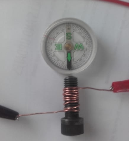
And for anyone wondering what my incompetence level is, here is my first learning experiment :)

incompetence_level_jly9ux.jpg


I will never forget this now after doing it in person. All those left and right hand rules were doing my head in. I now know if I wind a wire onto a common right hand threaded screw, and I treat the screw head as the ground, the end of the screw creates a South pole.
 
If you're wanting to learn about HF transformer design then the old Philips (Ferroxcube) MA01 databook isn't a bad starting point. They turn up from time to time because no one wants paper books anymore.

The text 'Soft Ferrites' by Edgar Snelling is a little dated in terms of materials but is a superb reference on ferrite transformer and inductor design. The newer power ferrites such as 3C90 and 3C95 aren't listed but the principles all still apply. It's long out of print and used copies command a fair premium which is testament to its quality.

Ferroxcube's own website looks worth a browse - I haven't been in the power electronics game for a good few years but from a quick look on their website they have some reference material and some sort of design tool / design aid which you can download.
 
A very commendable approach!

If you find the TDK/EPCOS 600+ pages hard to digest in one or two bites, I recommend Jim Williams' (LT staff scientist who sadly passed away when wrestling with a Fluke scope's SW problems, my guess) paper on switchers. I will look for it. A quote: "If the core feels right, has a nice weight and the Windings seem to be able to carry the current needed, then look no further. Just try it!"

I will look for that paper (a few pages) for you.

Good luck. And remember that the North Pole actually is a South Pole. By definition.

Gunnar Englund
--------------------------------------
Half full - Half empty? I don't mind. It's what in it that counts.
 
I'm not sure there's much DC-DC going on, inside a strobe light. As seen in or the objective is to get the electrical pulse to stretch out, but still be a pulse that's long enough for the light to register with your eyes.

TTFN (ta ta for now)
I can do absolutely anything. I'm an expert! faq731-376 forum1529 Entire Forum list
 
Thank you for your encouragement.

@IRstuff, my timing light is powered from the car battery, and steps the voltage up to about 350V, (via the DC-Dc converter) and stores it in a 2.2µF cap (450V), until it gets triggered by the inductive pickup (attached to the HT lead), by means of a SCR, which dumps the charge through another device (I'm guessing another transformer), and subsequently to the "bulb" for want of a better word.
 
GE said:
And Bob Pease, who died when returning home from Jim's funeral ceremony.

That was a very sad week. Several of us in my office were in mourning, those that knew of them.

Somewhere I have a letter from Bob Pease.
 
Status
Not open for further replies.
Back
Top