Continue to Site

Eng-Tips is the largest engineering community on the Internet

Intelligent Work Forums for Engineering Professionals

  • Congratulations KootK on being selected by the Eng-Tips community for having the most helpful posts in the forums last week. Way to Go!

transformer phase shift - how to measure with oscilloscope 3

Status
Not open for further replies.

MRSSPOCK

Mechanical
Aug 29, 2010
303
I know this might seem like a schoolboy level question, but I'm afraid I'm stuck.

If I have an unknown transformer and what to determine if there is a phase shift, how can I do it with my two channel scope, considering both channels use the common ground, and so by connecting two channels I am really creating a direct physical connection between the two otherwise isolated primary and secondary coils.

Thanks

I think I am going to be embarassed by the simple answer.
 
Replies continue below

Recommended for you

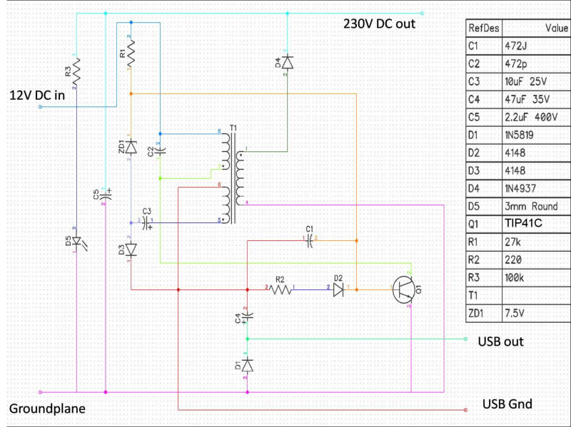
Hopefully this is clearer.

CIRCUIT_AND_PART_LIST_ljibd3.jpg
 
@ skogsgurra

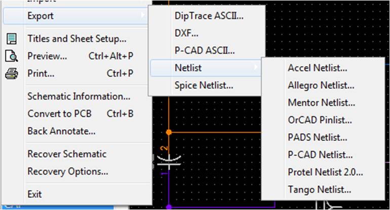
Diptrace has some export options.

Do any of these provide a means to create a file to run LTSPICE ?

I heard of LTSPICE but never used it or seen it used.

dip_exports_fmtmmn.jpg
 
Spice Netlist should work. LT Spice is a "Clean" Spice with a huge library of (mostly) Linear's Components. But also quite a few "generic" components. Give it at try. You can't lose - if your time isn't extremely valuable...

Gunnar Englund
--------------------------------------
Half full - Half empty? I don't mind. It's what in it that counts.
 
So, I had a go with LT Spice, but can't seem to get the transformer to output anything.
To be honest, Im not so sure I've set it up correctly.
Would anyone care to try running this please.
There are 4 components I haven't selected exactly properly as I couldn't find the specific components, but am confident the others are ok.

C1
C2
D4
Q1

Then I'm not sure if I have configured T1 correctly.

The first portion of code below is the code generated and stored in the *.net file.
I see it lists .model NPN, then PNP. I don't know why that is.


* \\PC1\Users\mrsspock\My Documents\LTspiceXVII\Draft1.asc
R1 N002 N003 27k
R2 N010 N006 220
R3 N001 N009 100k
C1 N003 N006 0.0047µ V=200 Irms=247m Rser=0.679706 Lser=0 mfg="KEMET" pn="C1210C472K2RAC" type="X7R"
C2 N002 N005 0.0047µ V=200 Irms=134m Rser=1.30834 Lser=0 mfg="KEMET" pn="C0603C472K2RAC" type="X7R"
C3 N008 N007 10µ V=25 Irms=39m Rser=2.8 Lser=0 mfg="Nichicon" pn="UPR1E100MAH" type="Al electrolytic"
C4 N011 N006 47µ V=35 Irms=115m Rser=1 Lser=0 mfg="Nichicon" pn="UPR1V470MPH" type="Al electrolytic"
C5 N001 0 2.2µ V=100 Irms=22m Rser=9.8 Lser=0 mfg="Nichicon" pn="UPR2A2R2MAH" type="Al electrolytic"
Q1 N005 N003 0 0 2N2222
D1 0 N011 1N5819
D2 N010 N003 1N4148
D3 N007 N006 1N4148
D4 N004 N001 RF01VM2S
D5 N009 0 QTLP690C
D6 N007 N003 BZX84B7V5L
L1 N005 N002 100µ
L2 N006 N008 400µ
L3 0 N004 40000µ
V1 N002 0 12
.model D D
.lib \\PC1\Users\mrsspock\My Documents\LTspiceXVII\lib\cmp\standard.dio
.model NPN NPN
.model PNP PNP
.lib \\PC1\Users\mrsspock\My Documents\LTspiceXVII\lib\cmp\standard.bjt
* 300V DC out
* USB Gnd
* USB out
* Gnd
* 12V DC in
;op
K1 L1 L2 L3 1
.op
.backanno
.end


**********************
and below here is the data from the asc file - the circles are only there to remind me that those features need revisited / corrected
**********************

Version 4
SHEET 1 1920 824
WIRE -32 -640 -144 -640
WIRE 1312 -640 -32 -640
WIRE 1616 -640 1312 -640
WIRE 96 -512 -640 -512
WIRE 192 -512 96 -512
WIRE 96 -432 96 -512
WIRE 1312 -400 1312 -640
WIRE -144 -352 -144 -640
WIRE 96 -224 96 -352
WIRE 1024 -224 96 -224
WIRE 96 -192 96 -224
WIRE 192 -176 192 -512
WIRE 480 -176 192 -176
WIRE 1312 -128 1312 -336
WIRE 1312 -128 640 -128
WIRE 192 -96 192 -112
WIRE 480 -96 192 -96
WIRE 480 -64 272 -64
WIRE 1312 -48 640 -48
WIRE 96 16 96 -128
WIRE 288 16 96 16
WIRE 480 16 352 16
WIRE -640 32 -640 -512
WIRE -32 48 -32 -640
WIRE 192 96 192 -96
WIRE 1168 96 192 96
WIRE -144 192 -144 -272
WIRE 752 256 416 256
WIRE 1024 256 1024 -224
WIRE 1024 256 816 256
WIRE 96 288 96 16
WIRE 1168 336 1168 96
WIRE 96 384 96 352
WIRE 272 384 272 -64
WIRE 272 384 96 384
WIRE 416 384 416 256
WIRE 416 384 272 384
WIRE 640 384 416 384
WIRE 880 384 720 384
WIRE 1024 384 1024 256
WIRE 1024 384 944 384
WIRE 1104 384 1024 384
WIRE 416 432 416 384
WIRE 416 528 416 496
WIRE 1488 528 416 528
WIRE 416 576 416 528
WIRE -640 704 -640 112
WIRE -144 704 -144 256
WIRE -144 704 -640 704
WIRE -32 704 -32 112
WIRE -32 704 -144 704
WIRE 416 704 416 640
WIRE 416 704 -32 704
WIRE 1168 704 1168 432
WIRE 1168 704 416 704
WIRE 1312 704 1312 -48
WIRE 1312 704 1168 704
WIRE 1488 704 1312 704
WIRE -144 784 -144 704
WIRE 272 784 272 384
WIRE 1488 784 272 784
FLAG -144 784 0
SYMBOL res 80 -448 R0
SYMATTR InstName R1
SYMATTR Value 27k
SYMBOL res 736 368 R90
WINDOW 0 0 56 VBottom 2
WINDOW 3 32 56 VTop 2
SYMATTR InstName R2
SYMATTR Value 220
SYMBOL res -160 -368 R0
SYMATTR InstName R3
SYMATTR Value 100k
SYMBOL cap 816 240 R90
WINDOW 0 0 32 VBottom 2
WINDOW 3 32 32 VTop 2
SYMATTR InstName C1
SYMATTR Value 0.0047µ
SYMATTR SpiceLine V=200 Irms=247m Rser=0.679706 Lser=0 mfg="KEMET" pn="C1210C472K2RAC" type="X7R"
SYMBOL cap 176 -176 R0
WINDOW 0 46 21 Left 2
WINDOW 3 49 63 Left 2
SYMATTR InstName C2
SYMATTR Value 0.0047µ
SYMATTR SpiceLine V=200 Irms=134m Rser=1.30834 Lser=0 mfg="KEMET" pn="C0603C472K2RAC" type="X7R"
SYMBOL polcap 352 0 R90
WINDOW 0 0 32 VBottom 2
WINDOW 3 32 32 VTop 2
SYMATTR InstName C3
SYMATTR Value 10µ
SYMATTR Description Capacitor
SYMATTR Type cap
SYMATTR SpiceLine V=25 Irms=39m Rser=2.8 Lser=0 mfg="Nichicon" pn="UPR1E100MAH" type="Al electrolytic"
SYMBOL polcap 432 496 R180
WINDOW 0 42 57 Left 2
WINDOW 3 34 13 Left 2
SYMATTR InstName C4
SYMATTR Value 47µ
SYMATTR Description Capacitor
SYMATTR Type cap
SYMATTR SpiceLine V=35 Irms=115m Rser=1 Lser=0 mfg="Nichicon" pn="UPR1V470MPH" type="Al electrolytic"
SYMBOL polcap -48 48 R0
WINDOW 3 24 56 Left 2
SYMATTR InstName C5
SYMATTR Value 2.2µ
SYMATTR Description Capacitor
SYMATTR Type cap
SYMATTR SpiceLine V=100 Irms=22m Rser=9.8 Lser=0 mfg="Nichicon" pn="UPR2A2R2MAH" type="Al electrolytic"
SYMBOL npn 1104 336 R0
SYMATTR InstName Q1
SYMATTR Value 2N2222
SYMBOL schottky 432 640 R180
WINDOW 0 24 64 Left 2
WINDOW 3 24 0 Left 2
SYMATTR InstName D1
SYMATTR Value 1N5819
SYMBOL diode 880 400 R270
WINDOW 0 32 32 VTop 2
WINDOW 3 0 32 VBottom 2
SYMATTR InstName D2
SYMATTR Value 1N4148
SYMBOL diode 80 288 R0
WINDOW 0 -39 5 Left 2
WINDOW 3 -73 71 Left 2
SYMATTR InstName D3
SYMATTR Value 1N4148
SYMBOL diode 1328 -336 R180
WINDOW 0 28 74 Left 2
WINDOW 3 24 0 Left 2
SYMATTR InstName D4
SYMATTR Value RF01VM2S
SYMBOL LED -160 192 R0
WINDOW 3 -124 -2 Left 2
SYMATTR InstName D5
SYMATTR Value QTLP690C
SYMBOL zener 112 -128 R180
WINDOW 0 24 64 Left 2
WINDOW 3 88 -4 Right 2
SYMATTR InstName D6
SYMATTR Value BZX84B7V5L
SYMBOL ind2 464 -80 M180
WINDOW 0 36 80 Left 2
WINDOW 3 36 40 Left 2
SYMATTR InstName L1
SYMATTR Value 100µ
SYMATTR Type ind
SYMBOL ind2 464 -80 R0
SYMATTR InstName L2
SYMATTR Value 400µ
SYMATTR Type ind
SYMBOL ind2 656 -32 R180
WINDOW 0 36 80 Left 2
WINDOW 3 36 40 Left 2
SYMATTR InstName L3
SYMATTR Value 40000µ
SYMATTR Type ind
SYMBOL voltage -640 16 R0
WINDOW 3 24 44 Left 2
WINDOW 123 0 0 Left 0
WINDOW 39 0 0 Left 0
SYMATTR InstName V1
SYMATTR Value 12
TEXT 1640 -640 Left 2 ;300V DC out
TEXT 1536 784 Left 2 ;USB Gnd
TEXT 1512 528 Left 2 ;USB out
TEXT 1520 704 Left 2 ;Gnd
TEXT -760 -512 Left 2 ;12V DC in
TEXT 960 -448 Left 2 !;op
TEXT 488 -248 Left 2 !K1 L1 L2 L3 1
RECTANGLE Normal 576 48 544 -208 2
CIRCLE Normal 1440 -272 1200 -448 2
CIRCLE Normal 1248 464 1056 288 2
CIRCLE Normal 864 336 704 208 2
CIRCLE Normal 688 80 400 -288 2
CIRCLE Normal 336 -48 128 -240 2
 
That's true. There is no thermal noise in LT Spice. Try adding some low-level noise (which I havent been able to find in the component library) or a small pulse a few milliseconds ino the simulation run.

Gunnar Englund
--------------------------------------
Half full - Half empty? I don't mind. It's what in it that counts.
 
Is this not a basic oscillator which seems to run ok?

Version 4
SHEET 1 880 680
WIRE 128 16 -16 16
WIRE 240 16 128 16
WIRE -16 64 -16 16
WIRE 128 64 128 16
WIRE 240 64 240 16
WIRE 128 160 128 144
WIRE 240 160 240 144
WIRE 384 160 240 160
WIRE 432 160 384 160
WIRE 240 192 240 160
WIRE 384 224 384 160
WIRE 128 240 64 240
WIRE 176 240 128 240
WIRE -16 320 -16 144
WIRE 240 320 240 288
WIRE 240 320 -16 320
WIRE 384 320 384 288
WIRE 384 320 240 320
WIRE 240 352 240 320
FLAG 240 352 0
FLAG 432 160 vout+
FLAG 64 240 base
SYMBOL ind2 112 48 R0
WINDOW 0 -29 56 Left 0
WINDOW 3 12 -244 Left 0
SYMATTR InstName L1
SYMATTR Value 10µ
SYMATTR Type ind
SYMATTR SpiceLine Rser=0.001 Rpar=0 Cpar=0
SYMBOL ind2 256 160 R180
WINDOW 0 -29 54 Left 0
WINDOW 3 4 351 Left 0
SYMATTR InstName L2
SYMATTR Value 10µ
SYMATTR Type ind
SYMATTR SpiceLine Rser=0.001 Rpar=0 Cpar=0
SYMBOL voltage -16 48 R0
WINDOW 3 -15 58 Left 0
WINDOW 123 0 0 Left 0
WINDOW 39 0 0 Left 0
WINDOW 0 34 58 Left 0
SYMATTR Value 1.5
SYMATTR InstName V1
SYMBOL npn 176 192 R0
SYMATTR InstName Q1
SYMATTR Value 2N2222
SYMBOL res 112 144 R0
SYMATTR InstName R1
SYMATTR Value 1k
SYMBOL LED 368 224 R0
WINDOW 0 -54 -412 Left 0
WINDOW 3 1 -407 Left 0
SYMATTR InstName D1
SYMATTR Value NSPW500BS
TEXT 72 -136 Left 0 !K L1 L2 0.999999999999999999999
TEXT 48 -104 Left 0 !.tran 0 0.00003 0 startup
TEXT 128 256 Left 0 ;Base
TEXT 240 200 Left 0 ;Collector
TEXT 248 288 Left 0 ;Emitter
 
Well, I have done some editing to the LTSPICE file, and have whittled it away bit by bit, until I am left with nothing but a single inducter and a 12V DC supply.
But strangley, even then, when I run the simulation, it saturates instantly.
Obviously that isn't possible in reality.
I tried huge Henry values and it is exactly the same as with minute values.
Can someone please suggest what I might be doing wrong?

I have in my hand an actual inductor which is 16mH. When I connect this to a 12V battery it saturates in 10ms at about 1.9A
Surely something as simple as this should be easy to simulate, but even then when I model it, it also saturates instantly, so I am obviously not using LTSPICE properly.

Any suggestions?
Can anyone model that please, since it is only two components and takes ten seconds.
Thanks
 
I got it sorted.
The initial voltage needs to be set at 0V for the start of the simulation run.
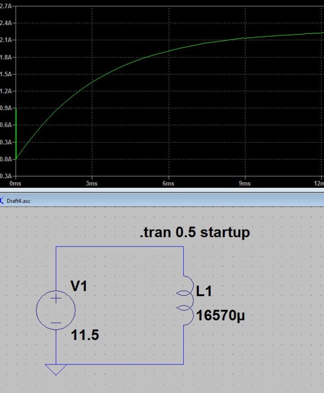
The simulation does match reality pretty well now.

inductor_saturate_mzjhdh.jpg
 
Steady state is not the same as saturation.
Your numbers are not working for me.
I calculate that it will take about 0.5 seconds to reach steady state.
Where did I go wrong?
12 Volts / 1.9 Amps = 6.32 Ohms.
6.32 Ohms x .016 Henrys = 0.1 = 1 Time constant
0.1 seconds x 5 = 0.5 seconds = 5 time constants to reach steady state.
When the magnetic core saturates, the inductor behaves as an air core inductor for further increases in voltage and the induction may drop be as much as 4 orders of magnitude for further increases in voltage.
Your trace is not showing saturation.

Bill
--------------------
"Why not the best?"
Jimmy Carter
 
Thanks.
Sorry, I thought they were the same.
So, I will rephrase it to say, my 16mH (motorcycle ignition) coil provides a steady state oscilloscope trace, (monitoring current with an amp probe), of around 1.9A after 10ms, when connected to a 12V 7Ah battery (which is registering about 11.5V - it needs a charge).
I measure the coil with an LCR meter, which gives me a series resistance value also of 5.03 ohms, and a capacitance of 15uF.
To be honest, I only just bought this LCR meter so I am still trying to make sure I am using it correctly, but that's the numbers it gives me at the minute. Those are the values I put into LTSPICE to get the trace shown in my last post.
 
A capacitance of 15 uF? Not possible. Interwinding capacitance is in the pF (millionth of a uF) order and total capacitance ocross all windings is even less. Did you use that capacitance in the Spice model? BTW, 11.5 V from a 2 A loaded 7 Ah ackumulator isn't bad at all.

Gunnar Englund
--------------------------------------
Half full - Half empty? I don't mind. It's what in it that counts.
 
oops... I was using the LCR meter incorrectly, so I have simply removed the parallel capacitance value.
The 4.9 ohms resistance was measured using a Fluke multimeter, and the 16.624mH using DER EE LCR meter.
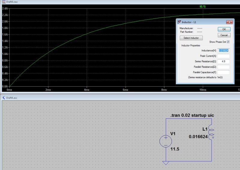
When I plug these values into LTSPICE, the results are pretty close to the trace as recorded in the real world on the scope.
I thought that was good, but I don't undestand the different equations shown above.
@IRstuff What should be 2.5ms ? Do you refer to the same quantity that waross says should be 500ms ?
Below is shown the values defining the inductor and the resulting trace.
inductor_mblowq.jpg
 
@IRstuff
Thanks. It makes a bit more sense now, and I now realise my confusing steady state with saturation. So then, 5 time constants of 2.5ms = 12.5ms which does agree with the simulation, and with the actual coil test. I didn't take any screen grabs of the actual coil test so I will set it up again soon to do that. Thanks everyone for bearing with me. I did state at the outset, that I do really possess quite a high level of incompetence :)
 
Waross said:
Where did I go wrong?
Thanks for setting me straight IRstuff.

Bill
--------------------
"Why not the best?"
Jimmy Carter
 
"I didn't take any screen grabs of the actual coil test so I will set it up again soon to do that"

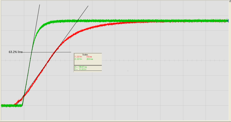
Sorry to have done that already. This shows the same inductor in two different time scales (5 and 20 ms/div):

image_dlhs35.png


Tha data are 10 ohms, 11.5 V and 19 mH. The effect of high initial permeability can be seen in the 5 ms/d curve where di/dt is low during the first few milliseconds and then goes into a more constant L region.
No saturation in this run, that would have shown as an increased di/dt near end of curve.

Gunnar Englund
--------------------------------------
Half full - Half empty? I don't mind. It's what in it that counts.
 
Hmm… Have to check the numbers. I measured inductivity with 50 Hz AC. Doesn't seem right.

Gunnar Englund
--------------------------------------
Half full - Half empty? I don't mind. It's what in it that counts.
 
Status
Not open for further replies.

Part and Inventory Search

Sponsor