Eng-Tips is the largest engineering community on the Internet

Intelligent Work Forums for Engineering Professionals

Transformer Soak Test HV & LV 2

Status
Not open for further replies.

PSEng01

Electrical
Dec 22, 2019
9
0
0
NZ
New transformer usually go through soak test (as in no load) for a couple of hours before load is introduced. The tests that I have seen are energized from HV, leaving downstream LV switch open (of course, both HV and LV winding will be energized).

Recently there is a proposal from a contractor to perform this test twice, first energize from HV winding and second time is energizing from LV winding (as in, opening a HV breaker/switch somewhere).

I do not see the benefit of doing this test from LV end. Anyone else doing the same and have other thoughts?
 
Replies continue below

Recommended for you

What winding configuration and what protection? A delta-wye withe just overcurrent on the delta high-side would be completely unprotected if energized from the wye low-side. A transformer with full differential and breakers on both side might not care. Not much to gain from the second soak though.
 
Thank you David, it is Dyn 33/11kV and will have full transformer differential protection and you are right there will be no protection, HV breaker's overcurrent is set very high to tackle in rush so won't react either.
Thought so too about 2nd soak... hmm...
 
As a broader question, I'm interested in the science behind a 'soak test' - if there is any - and where it is documented. Is the 'soak test' something some operators do because it just instinctively feels right, in much the same way that they'd allow a boiler / steam system to warm up gradually?
 
Being both a stationary "engineer" and a transmission system operator, I wonder the same thing; I've got lots of experience with differential expansion in steam systems and have dealt with temperature ramp rates for years, but have never heard any explanation, either logical or farfetched, as to the actual science behind trafo soak tests; all that happens is that directions come from Engineering On High stipulating the side of energization and duration of soak tests.

As to the protection issues, the way it's been explained to me, modern programmable trafo protections can be set to have a sort of inverse time curve that follows the magnetizing curve characteristics of the bank, so the idea that in this day and age a trafo would be deliberately left unprotected while being placed on potential or during a soak test, and that there is no way to mitigate this, is ludicrous in the extreme; besides, trafos / regulators / phase shifters / "quadrature boosters" are very expensive and labour-intensive products, and the very idea that such a risk would be taken with such a valuable asset would be enough to give the bean counters gas.

CR

"As iron sharpens iron, so one person sharpens another." [Proverbs 27:17, NIV]
 
A transformer being soaked should never be left unprotected. If the protection is only overcurrent that only functions for faults in one direction then the soak current must go in that direction.

My understanding is that soaking is intended to allow thermal stability before placing load on the transformer. If there's any risk of latent issues with the transformer it is better to have it fault and be tripped with only the transformer affected. A soak to thermal stability also provides a good opportunity to verify that all of the radiators are at approximately the same temperature before putting full load on the transformer.
 
Agree with David that some protection is mandatory. I don't think the transformer is going to get that warm sitting at mo load, but it allows time for gross problems to present themselves. But energizing a large power transformer after a long-distance shipment and installation is always a bit scary. If you have never heard the core noise on a brand new transformer, it can be shockingly loud and bizarre. The core and windings are getting settled in after being jostled and jarred during shipment. Also, voltage measurements should generally be taken prior to any load being applied.

IIRC, this is generally a recommendation of the transformer suppliers, but I don't have anything at hand to support that.
 
We placed three 345kV/138kV, 500MVA Autos in service recently - all sister units. I'm told the cost was approx $4M USD each. A 24 hour soak was performed from the HV side. As one would expect with units of this size, fully redundant differential protection was available. The units are equipped with Electronic Temperature Monitors communicating via SCADA, as well as conventional analog devices. I made a trip to the site around 24 hours to check on the temperatures. Starting from ~ o Deg C, all three managed to warm up to around 17 C, in a maybe 5 C ambient. An IR camera was used to check radiators. Not mentioned yet, but DGA samples were taken around the 24 hour mark - I believe this is fairly standard for units this size.

It's my understanding that the 24 hour soak is part of the commercial agreement between the owner and the OEM, or at least in this case it was, for acceptance of the units (and final payment).

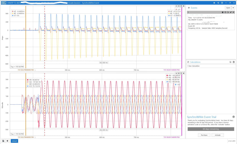
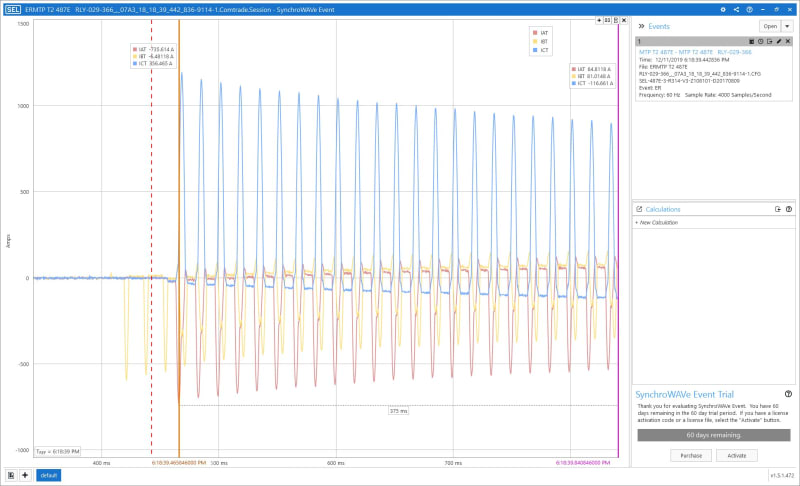
We used synchrophasors to monitor the voltage dip during energizing. Unit #1 had ~ %2 and 2 & 3 closer to 5% dip. We had demagnetized #1 as part of a NLTC tap change earlier.

As far as the OP question on both ways / sides, I'm not sure if I see any value. In some cases the inrush may be too much. I suppose that depends on the size of the transformer and the system.

I did "clean up" at a IPP peaker plant years ago. The first of 4 345/13.8kV/13.8kV 200 MVA sister units was energized. The newly hired plant operators logged their hourly inspections of the Top Oil going well past 120 C prior to the unit faulting. Unfortunately the first commissioning contractor forgot to walk things down and the Multilin 745 CT's were left shorted. Two stations down the line 51N cleared the fault after 33 cycles. The DGA's were not ordered "rush" and when the results came back after the failure, acetylene was several hundred ppm.

The shots below are during tuning of the Synchronous Closing devices on the GCB's after a successful soak period (837 FLA).
345kV-500MVA_Inrush_t2-with_345-138_voltage_LI_wbvy1b.jpg


345kV-500MVA_Inrush_t2_ntrl9n.jpg
 
A commissioning engineer told me one reason for the soak on a new unit is to vibrate any remaining gas bubbles out of the windings.

I agree with DPC that the thump and noise on first energization of a new, large transformer is loud and a little scary. You can feel the magnetic thump from the inrush current and the hum always seems louder than normal.

Maybe there is no valid technical reason for a soak test, but why put a new unit under load immediately without some verification that it won't blow up when energized.
 
1)No Wilson, soak test is not for removing air bubbles. Air bubbles are equally dangerous at no-load and as at load, no more serious. All air bubbles will get dissolved in to oil during the settling time (minimum time specified by OEM or IEEE standard from finish of oil processing to energization) Transformer shall be energized only after all the air bubbles are removed or dissolved in to oil. Once a 132 kV transformer was re-energized (after internal inspection) before the min settling time as the aluminum smelter manager wanted to commence production with out delay. Within 12 hours transformer failed and the failure point was between two discs of HV winding -a potential point for sticking air bubbles.
2) Soaking test is specified in IEEE C57.93- Installation and maintenance of Transformers with different minimum periods for different voltage classes. The need for this test is to reduce or limit the internal damage in transformer failure, in the unlikely event of any defect or mistake (not detected or noticed during inspection/electrical tests at site)that might have occurred during transport/installation/ processing of transformer. Such cases are not common, but not rare. It is also expected that OEM engineer will be inspecting for abnormal noises/ vibrations everywhere in the transformer-tank, tap changer part etc during the soak test.
3) No need or advantage for energizing from both sides during soak tests. Voltage will anyway get induced in both windings !
4) The said rated EHV auto-transformer with OLTC is shipped from Indian factories at less than 1.5 MUSD!
 
A special "soaking test" that engineers have to be careful is that of Generator Transformer. In Power stations construction work will be going ahead in several fronts and most of the time, GT will be ready for energization, but generator side will not be ready. The project managers will like to back charge the GT from HV side and do soak test to make sure GT is Ok. In case they wait for Generator to be ready and commission in the normal way and then GT fails the whole project will have set back.

Such back charging can be quite troublesome for transformer due to the high voltage ratio between HV to LV. The following protocol can be used to prevent failures in such large EHV GTs,
1) Energise at highest voltage tap- it will result in lower flux density and less inrush current. Since the whole tap winding will be in circuit without floating,chances of part winding resonance and consequent dielectric failure in winding can be avoided.
2) To take care of the transferred switching surges causing flash over at LV bushings, keep the surge absorber and LA of generator (or Generator CB)connected to the LV side of Generator Transformer.
 
Weird; transmission system operators think of "back-energizing" a trafo as being from the low side, while GS operators and engineers think "back-potting" from the HV grid to an open set of LV links is very abnormal/off the beaten path; I guess it's all a matter of perspective...like Einstein said, "It's all relative."

CR

"As iron sharpens iron, so one person sharpens another." [Proverbs 27:17, NIV]
 
I agree with thermionic1 about the agreement between the owner and OEM - there is usually some sort of arrangement in place.

My believe is that soak test is to :
1. allow the entire volume of oil to slowly circulate through within the transformer and;
2. allow oil to soak through the insulation (paper) fully.

Not sure whether insulation paper is more resistive to liquid wicking process (especially thermally upgraded ones), would love to witness this one day. If it does then that explains not energizing on load right away because the cooling process is not at its optimum yet.

This all makes sense to me because of the term "soak" and also the duration of such tests usually lasting hours. Imagine oil moving slowing from bottom to top of the transformer with minimal temperature gradient due to no load... I wonder if anyone (besides manufacturers perhaps) have some ideas on how much time it takes for the entire oil volume to fully circulate through their transformer?

On the side it is also a peace of mind for the owner, it is more like a milestone check in the commissioning process (I think!)
 
No,soak test(charging at no-load for 8 (below 230 KV)-12 hours(230 KV &above) as per Table 6 of C57.93-2019) is not for soaking the paper or for moving the oil around the tank. Such hold time for oil impregnation is given prior to energization and not after energization (Table 2 of above standard 12-72 hours as hold time for 69-765 kV Transformers).To quote from standard-

Energize the transformer and hold at rated voltage at no load for a period according to NOTE 1 of Table 6. While
this period of energization at no load is not required, it is helpful to understand and evaluate the transformer
in this condition prior to applying load. During this energizing period, before loading the transformer, it is
recommended to perform the following surveillance actions:
— Check for excessive audible noise and vibration.
— Monitor temperature of liquid, recording to be taken at time intervals (every hour) until stabilization.
— Monitor temperature of winding hot spots, recording to be taken at time intervals (every hour) until
stabilization.
— Monitor ambient temperature.
— Operate and check performance of LTC through all positions, without exceeding the rated voltages of
surge arresters or other connected components (if applicable).
— Operate and check performance of cooling pumps and fans (if applicable).
— Inspect for liquid leaks and check all liquid level indicators and gas detector relay (if applicable).
— Take liquid samples at the beginning and the end of the energizing period to retest for moisture content
and DGA. Liquid sampling in LTC diverter switch compartment (if applicable) could be valuable for
investigation and monitoring purposes. (See NOTE 2 of Table 6.) Unquote
 
Status
Not open for further replies.
Back
Top