Hi Guys,
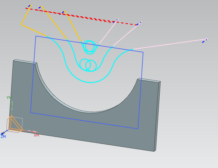
I want to profile a piece of steel as shown in the image. You can see the blank and the final part which has a semi-circle cut from the stock perimeter. Is it possible to remove the main semi-circle of material using a trochoidial tool path and not by using the full width of the tool around the perimeter of the part? Cavity mill will work but
as shown I can only get it to do a conventional slot type toolpath. To get a trochoidial toolpath do I have to model in the slot, apply the trochiod cutting parameters from there and do it that way? Is there an operation or technique that will do what I want without modifying the part?

cheers,
James
I want to profile a piece of steel as shown in the image. You can see the blank and the final part which has a semi-circle cut from the stock perimeter. Is it possible to remove the main semi-circle of material using a trochoidial tool path and not by using the full width of the tool around the perimeter of the part? Cavity mill will work but
as shown I can only get it to do a conventional slot type toolpath. To get a trochoidial toolpath do I have to model in the slot, apply the trochiod cutting parameters from there and do it that way? Is there an operation or technique that will do what I want without modifying the part?
cheers,
James
")