Continue to Site

Eng-Tips is the largest engineering community on the Internet

Intelligent Work Forums for Engineering Professionals

  • Congratulations SSS148 on being selected by the Eng-Tips community for having the most helpful posts in the forums last week. Way to Go!

Trolley Design / Safety / Toppling.

Status
Not open for further replies.

Mallon

Mechanical
Nov 4, 2010
4
I am after some help on the design of a trolley. We are buying out a standard trolley which can hold up to 500kg. Weight of the trolley is 114. The load the trolley will be carrying is 410kg.

I have attached a picture below. As you can see the load is quite tall. We have worked out the Centre of gravity using manufactured models of the valve/chute.

The chute is connected to the valve. The trolley will be wheeled in and fastened to the underside of the valve using bolts so the load is fixed.

trolley1_ltlrty.jpg


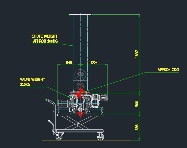
Can anyone give me a hand on calculating the force required to topple the trolley. The trolley will only be moving a very short distance at walking speed.
 
Replies continue below

Recommended for you

What are the dimensions between the caster wheels from the right view? Depending on the width between the wheels, it might be more likely to tip in that direction since it appears the right most casters are non-swiveling types will have friction holding them in place during a side load. I believe you need to figure out the force required to move the CG past the center axis of the casters. The CG will be lifted since it travels in an arc about the pivot point (casters).

Kyle
 
My concern would be flexibility and play in the joints of the cart that would allow tilting of the load before the cart even moves. Make sure it's a stout cart to begin with.
 
Is that a scissor jack underneath the platform? Can you drop that all the way down when in motion? That will help stability immensely no matter what else the numbers are. Also, what is the quality of the floor? Perfectly smooth and flat or are there pits and cracks to trap those wheels?

----------------------------------------

The Help for this program was created in Windows Help format, which depends on a feature that isn't included in this version of Windows.
 
The most likely toppling scenario is if a pebble gets wedged under the wheel, and calculating that is nigh on impossible.

Cheers

Greg Locock


New here? Try reading these, they might help FAQ731-376
 
Greg,

I'm a sparky by training, so set me straight on this if I need it.

Can't you do the "pebble under the wheel" scenario in two stages:

1. Compare the geometry with all four wheels on the floor and with the trolley perched on two wheels with the cg directly over the line joining the contact patches of the two wheels. Calculate the difference (h) in cg height above ground for the two scenarios (h)

2. Assume all the kinetic energy of the moving trolley gets converted into potential energy when the trolley trips. If

1/2 v2 > g.h​

the trolley is likely to topple.​

or is that a gross over-simplification.

A.
 
That's certainly a worthwhile approach, interestingly it'll give a do not exceed speed, which is NOT what I'd expected as an answer... but I don't know what I was expecting, now.

Cheers

Greg Locock


New here? Try reading these, they might help FAQ731-376
 
But, that seems to me to come up with an overly conservative value for forward speed, since you pretty much have to go out of your way to get all of your KE into a sideways force. The classic two wheel stunt requires a fairly high ramp to get an automobile to tip onto two wheels. And, the ramp will be much taller than a "pebble."

Nevertheless, it would seem to me that you could use the ramp stunt to analyze how high a ramp is required to tip the trolley.

However, the force required to tip the vehicle will depend on where the force is applied. You could certainly use the PE of the tipped trolley equated to the force*lever arm distance to come up with a range of forces, with the lowest force being applied to the very top of the structure.

TTFN
I can do absolutely anything. I'm an expert!
homework forum: //faq731-376 forum1529
 
Mallon,

I asked this question in the structural forum.

thread507-255357

--
JHG
 
Is the load just resting on the small flange? It will be pretty easy for it to fall over no matter how large the trolley cart's foot print.
 
As Irstuff implies, you can calculate the tipping moment relatively easy - in the orientation you show treat one of the wheels as the fulcrum and the weight as force and there you go.

What force engenders an equivalent moment will depend where it is applied.


Posting guidelines faq731-376 (probably not aimed specifically at you)
What is Engineering anyway: faq1088-1484
 
Instead of using that handle which adds to the overturning moment, you could use a push bar mounted to the base of the cart like the push handle on a Cozy Coupe.

Off the wall but did you think of air lifts?
 
From the sketch it certainly appears the cg of the load is above the handle height the force will be applied to move the cart. This is not a good situation. Another problem is the location of the swiveling rear casters. If they are not aligned with the fixed front casters when the trolley is initially pushed, this will increase the amount of force that must be applied to get the trolley moving. Probably a good idea to add some device to ensure the load is lowered as much as possible before moving, and also increase the wheelbase/track dimensions of the casters.
 
Some things to consider:
1) compliance in the scissor. While they are pretty stable in the Z direction, they aren't completely stiff in rotation and will allow the platform to tilt fore and aft; not much but it contributes
2) if the valve is not bolted to the platform it can slide under acceleration; the farther it slides the greater the moment on the platform and the greater the tilt, which can make it worse.
3) the footprint of the valve seems small. Even if the platform doesn't tilt, the valve might
4) if the floor is not level there will be a small component of tilt that can make things worse
5) unevenness in the floor can produce enough accelerations to vibrate the valve off the platform even when there isn't enough energy to tilt the item
6) check overhead clearances. Snagging that on a door frame or plastic drop opening could pull it loose
7) check the floor for holes and cover plates. drop a wheel into one of those and and the thing will go over.

Don't let this happen to you -
 
Thanks for all the replies guys. Sorry I didn't get any notifications anyone had replied.

Yes it is a mobile scissor lift rate for 500kg so the load should be no problem and the load is centered according to manufacturer reccomendations.

The width between castors in the right view is approx. 600. The back castors are swivel the front are fixed.

The floor is relatively smooth no pits or debris but there is a slight fall for drainage.

Dgallup I agree I will make sure to address in a work instruction that the table must be lowered to its lowest height before movement. Its lowered height is 360 which will bring the cog below the top of the handle. Also making sure worker understands trolley castors must be inline before valve is fixed to trolley.

3ddave . Yes the valve will be bolted to the platform. The valve has the same flange on top as bottom and is cast stainless steel 316. I will check the floor don't think
there are any drains. I am going to make sure a route and a docking station is in place for the trolley.

The trolley will probably rarely get used it is only for 3/ 6 monthly maintenance and cleaning of the chute and hopper above.


Status
Not open for further replies.

Part and Inventory Search

Sponsor