Navigation
Install the app
How to install the app on iOS
Follow along with the video below to see how to install our site as a web app on your home screen.
Note: This feature may not be available in some browsers.
More options
Style variation
-
Congratulations TugboatEng on being selected by the Eng-Tips community for having the most helpful posts in the forums last week. Way to Go!
You are using an out of date browser. It may not display this or other websites correctly.
You should upgrade or use an alternative browser.
You should upgrade or use an alternative browser.
True position applied to planes 3
- Thread starter Rwelch9
- Start date
- Status
- Not open for further replies.
Burunduk
Mechanical
- May 2, 2019
- 2,580
chez311, I know that the standard (at least the 2009 version) does not prohibit using CF on features interrupted by protrusions.
I just consider it a bad practice.
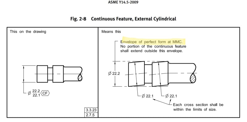
I notice that people treat CF as only a way to say "treat these X features as 1 feature" but they forget or don't know that it is actually a specific geometrical requirement with an intent that is not necessarily appropriate for every case where the designer decides to communicate that sentence with a symbol. As I mentioned (and I didn't see it addressed in the thread you linked to), the standard requires that the continuous feature must conform to rule #1 by fitting within a single continuous MMC perfect form envelope (see the figure below). Rule #1 itself is the most general and basic way to ensure fit under worst-case assembly conditions between mating parts (although not stated so anywhere in the standard). Applying rule #1 on several separated surfaces simultaneously makes sense for example for a shaft with slots that is designed to entirely fit within a single bore in a mating part. It makes much less sense for features with protruding interruptions.
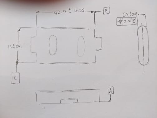
From the practical standpoint, if for example it will be desired to make a hard gage for rule #1 inspection for the 42.9+/-0.05 width in the OP which apparently has a CF symbol applied to it ( not shown in the sketch but mentioned somewhere in this thread), the gage will reject the part. Perhaps this is less of a problem with a CMM or some other advanced metrology devices and software aids, I don't know. But I think anyway that application of requirements should be carefully considered, and it is not likely the case here.
Rwelch9, can you use the CMM to "virtualize" a 42.95 wide MMC gage to the full 15.1 maximum height of the part that will only detect interference between the intended feature and it's MMC boundary, and "ignore" interference of the protruding tabs with that boundary?
Relation of CF with rule #1:

It makes much less sense for features with protruding interruptions.
In some cases perhaps. I can easily imagine a mating feature which has corresponding interruptions/gaps where the feature has protrusions - or where the mating assembly has parts which assemble in pieces around the protrusions, think of the bearing journals on a crankshaft or camshaft. In this case the faces may mate up against a plate or surface which has a hole/slot in it.
Perhaps this is less of a problem with a CMM or some other advanced metrology devices and software aids
It almost certainly is less of an issue. OP stated several times they make extensive use of a CMM. LMC/LMB utilizes the principle of a boundary passing through the material and inside the material and these material/boundary conditions are certainly able to be inspected, just not with hard gauges. (not that hard gauges are not possible in this case with <CF>, just perhaps more complex).
can you use the CMM to "virtualize" a 42.95 wide MMC gage to the full 15.1 maximum height of the part that will only detect interference between the intended feature and it's MMC boundary, and "ignore" interference of the protruding tabs with that boundary?
I am no CMM expert but I can say with a very high degree of certainty that its possible. One could certainly establish a UAME for all the cases of my (25 Oct 19 14:47) post on the referenced thread even though it passes through a protrusion.
Relation of CF with rule #1:
"no portion of the continuous feature shall extend outside this envelope"
It doesn't say "no portion of the part". The envelope applies only to the surfaces/features to which the <CF> feature applies.
- Thread starter
- #43

Chez311 + Burunduk
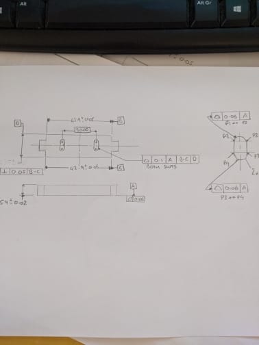
Please see attached image , would this be an acceptable DRF.
Burunduk , the CMM software i am using at the moment does not have the capabilities you mentioned. regarding Datum feature B from the old sketch , you could take a series of points on 4 planes then try look at the individual points and create a plane from the highest points etc but very difficult to do.
I think PCdmis would have the capability once you have took points on the planes , create a virtual simulator matching the maximum boundary.
The software i use at the moment can only use the least squared method for planes . So using virtual simulators will always have a degree of uncertainty.
Thanks
R
-
1
- #44
Rwelch9,
A few notes:
-the perpendicularity tolerance on the width D should be removed. To evaluate this requires the issues discussed above in establishing a UAME for this feature (or parallel elements).
-I personally think a double leader from a single profile tolerance accompanied by 2X would be sufficient for the 2X radii. Your method is not wrong, just a little unwieldy, but I see why you might want to since they are tangent. The 2X and leaders would make it pretty clear though that the tolerance only applies to the radii. It might even be worth considering applying this profile tolerance all around this profile though.
-A should probably be the width as previously suggested.
-the "BOTH SLOTS" notation could be simply replaced by 2X in front of the FCF
Seems to me you could essentially treat all the points sampled from the 4x interrupted surfaces as if they were from 2x continuous surfaces.
A few notes:
-the perpendicularity tolerance on the width D should be removed. To evaluate this requires the issues discussed above in establishing a UAME for this feature (or parallel elements).
-I personally think a double leader from a single profile tolerance accompanied by 2X would be sufficient for the 2X radii. Your method is not wrong, just a little unwieldy, but I see why you might want to since they are tangent. The 2X and leaders would make it pretty clear though that the tolerance only applies to the radii. It might even be worth considering applying this profile tolerance all around this profile though.
-A should probably be the width as previously suggested.
-the "BOTH SLOTS" notation could be simply replaced by 2X in front of the FCF
the CMM software i am using at the moment does not have the capabilities you mentioned. regarding Datum feature B from the old sketch , you could take a series of points on 4 planes then try look at the individual points and create a plane from the highest points etc but very difficult to do.
Seems to me you could essentially treat all the points sampled from the 4x interrupted surfaces as if they were from 2x continuous surfaces.
- Thread starter
- #45
Chez311,
Regarding what i now placed as Datum D , looking back through your discussions with Burunduk, could i use to parallel planes pushed up against the radii as Datum feature simulators. ?
I will incorporate your other suggestions also.
Thanks
R
Regarding what i now placed as Datum D , looking back through your discussions with Burunduk, could i use to parallel planes pushed up against the radii as Datum feature simulators. ?
I will incorporate your other suggestions also.
Thanks
R
I haven't been following this discussion closely, but maybe the thinking here was to maintain the relationship of the datum features to each other. The profile tolerance of 0.1 references A, B-C, D so it's good practice to use GD&T to relate D to the higher-order datum B-C.chez311 said:The perpendicularity tolerance on the width D should be removed.
In a similar way, I might even suggest something to relate datum features B and C back to A, although I know this will clutter up the drawing some more. Just my thoughts...
John-Paul Belanger
Certified Sr. GD&T Professional
Geometric Learning Systems
-
1
- #47
could i use to parallel planes pushed up against the radii as Datum feature simulators
Yes, this is how you have it specified (width as a datum feature).
Thinking back to your response about the issues with validating a continuous feature <CF> with your software, it seems more like you have issues with continuous features in general, not just ones that pass through a protrusion? Or perhaps ones that consist of multiple planar features specifically - which of the below would you have issues with?

JP,
I agree that may have been the intent, and in almost every other instance I would agree relating lower precedence datum features to higher order ones is not just good practice but required. This is because the features themselves which are utilized as a datum feature must be sufficiently accurate and controlled back to those of higher precedence. In this case you have a width which is derived from a feature which already has a tolerance back to these higher order datum features (radius profile to |A| which should probably be |A|B-C|). Evaluation of perpendicularity of this width results in an unstable UAME with no minimum, it seems to me this is unnecessary. As discussed previously D should not be referenced primary for this very reason.
I agree with this. Also now that I look at it, the tolerances that make up the radii should probably to |A|B-C| not just |A|.
I agree that may have been the intent, and in almost every other instance I would agree relating lower precedence datum features to higher order ones is not just good practice but required. This is because the features themselves which are utilized as a datum feature must be sufficiently accurate and controlled back to those of higher precedence. In this case you have a width which is derived from a feature which already has a tolerance back to these higher order datum features (radius profile to |A| which should probably be |A|B-C|). Evaluation of perpendicularity of this width results in an unstable UAME with no minimum, it seems to me this is unnecessary. As discussed previously D should not be referenced primary for this very reason.
In a similar way, I might even suggest something to relate datum features B and C back to A
I agree with this. Also now that I look at it, the tolerances that make up the radii should probably to |A|B-C| not just |A|.
Burunduk
Mechanical
- May 2, 2019
- 2,580
Controlling the radii for profile of a surface with reference to |A|B-C| (or |A|B| if CF is applied) will eliminate the need for perpendicularity control shown in the last sketch. That's why I suggested it in my post from 15 Jun 20 02:39 and repeated the suggestion on 16 Jun 20 09:53. It was also repeatedly suggested to designate the 5.9 width as the primary datum feature (of size)-A.
Burunduk
Mechanical
- May 2, 2019
- 2,580
chez311, as far as I know, many experience issues related to CMM inspection dealing with concepts that were developed with fixed gages in mind: surface interpretation of MMC tolerances, datum shift, fixed boundaries of any kind, I'm not surprised by the difficulty with rule #1 for a continuous feature, especially with external interruptions.
- Thread starter
- #51
chez311 + Burnunduk
Yes you are correct regarding the CMM , multiple planar features is a problem . This is mainly due to the least squared algorithm used to generate a best fit plane.
As i says previously you can take individual points and try create a maximum boundary plane. This would mean for my software anyway that i could not run this is a CMM programme.
There is more sophisticated software's which can do this and are following ( trying ) ASME rules with regards to accurate virtual datum simulators.
I will apply the CF back into the drawing as for me this is easier on the drawing and will free up space also.
Fixed gauging is something i would really like to be able to incorporate into my thinking and methods of inspection.
what level of tolerance to you feel comfortable with achieving with fixed gauging and to what degree of certainty.
Thanks
R
Burunduk
Mechanical
- May 2, 2019
- 2,580
Rwelch9 said:I will apply the CF back into the drawing as for me this is easier on the drawing and will free up space also.
Then how do you intend to inspect that no portion of the interrupted feature violates a single continuous MMC envelope?
- Status
- Not open for further replies.
Similar threads
- Question
- Replies
- 9
- Views
- 1K
- Locked
- Question
- Replies
- 9
- Views
- 3K
- Locked
- Question
- Replies
- 4
- Views
- 1K
- Locked
- Question
- Replies
- 9
- Views
- 2K
- Replies
- 11
- Views
- 9K

