Continue to Site

Eng-Tips is the largest engineering community on the Internet

Intelligent Work Forums for Engineering Professionals

  • Congratulations SDETERS on being selected by the Eng-Tips community for having the most helpful posts in the forums last week. Way to Go!

True position applied to planes 3

Status
Not open for further replies.

Rwelch9

Mechanical
Apr 22, 2020
116
IMG_20200612_223343_knrvks.jpg

Hi ,


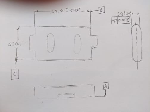
I have a couple of queries about the sketch i did .

Datum feature C would this be a derived line between the two axis of the radii at each end of the component

The True position call out ± 0.05 to Datum feature C , is this a valid call out ?

Thanks

R
 
Replies continue below

Recommended for you

Burunduk + Chez311

With regards to the datum simulators . If it was decided that it was parallel planes push against the radii , the mid plane of this would not give me dimension i am looking for.

Datum feature C

As a 3rd datum what would be the best way to accurately set up a Datum Ref frame .

On the CMM i can measure the two Radii and find the derived centre axis between the two axis of the radii.

I can also create a plane between points that make up the centre axis of both radii.

The CMM does have good options to try build a accurate DRF .

This one seems a bit trickier than usual.


Thanks

R


Either basic or directly toleranced - so what matters is not how it's applied "to the tolerances" is it?

I don't think I got across that nuance very well. What it boils down to is that it matters how the datum feature symbol itself is applied. A datum feature symbol applied to a width means a width-shaped datum feature. The inverse shape of the simulator is also width shaped.

If you believe otherwise, what do you think the simulator looks like for datum feature A of Y14.5-2009 fig 4-33?
 
If it was decided that it was parallel planes push against the radii , the mid plane of this would not give me dimension i am looking for.

What dimension are you looking for? From the rest of your response (as well as the prior ones) looks like you are caught up in the establishment of theoretical geometry. As I stated on one of your previous threads, this is really less important than your datum feature to simulator relationship - the creation of a certain dimension or axis/center plane can be done from any reference. It is your simulators which constrain your part, not these derived geometry - they are derived from your simulators, not the other way around.

As a 3rd datum what would be the best way to accurately set up a Datum Ref frame

Knowing how your part functions or mates in an assembly would be a first step. From this - determine what your datum features should be and from there what your simulators should look like.
 
chez311,
After thinking about it, a stance that I would adopt is that when the datum feature symbol is associated with a size dimension, the datum feature is whatever the dimension defines; in fig. 4-33 the basic 3 dimension is given between surface extremities that form line elements; two on the left side and another one offset from the first two. So this datum feature is simulated by two parallel planes. In the OP case, the 15+/-0.1 dimension defines the distance between opposed points on both surfaces that form together two opposed line elements, so the datum feature is these two imperfect opposed line elements (which are also one of the options the standard lists as a regular feature of size). I would agree that this datum feature should be simulated by two parallel planes that should be tangent to the surfaces of the radii on these imperfect opposed line elements. If this feature is used as a primary datum feature like in the position tolerance feature control frame in OP's sketch, then I agree this would be an unstable datum, although I don't know what to make of the fact that if the parallel planes are rocked to find the minimum separation, the points they contact would not be opposed other than at only one orientation of the planes. So technically there is only one "feature of size" condition for the simulation but I don't know if and how this can be controlled at inspection.

Rwelch9,
The position control FCF you showed in the sketch doesn't call out datum feature C as tertiary, but as primary (the only datum in the FCF). I'm afraid that according to what we just discussed it can not give you or the designer a centering datum reference for the 5.9 width. At best, it may attempt to provide an orientation constraint, which would be unstable. Is there an option for a change in the drawing?
 
Burunduk + chez311

I totally understand now about in that specific FCF datum C would be the primary Datum ( thanks for that )

Drawing changes may be possible .

How could you control the 5.9width tight like my sketch to ± 0.02 but the mid plane could vary slightly from the centre of the Radii.

That is the only questionable dimension i am struggling to both check and dimension .

The error between the mid plane derived from the 5.9 width at the centre of the radii


Thanks

R
 
Rwelch9,
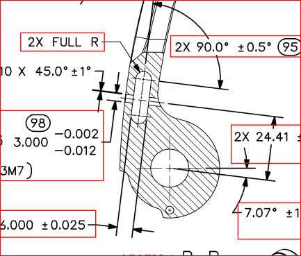
I wouldn't try to control anything tightly to the axes of the half-cylinders or control the axes of the half-cylinders tightly with reference to anything. The radii are 180° arc angle so it will be difficult or impossible to derive axes from them, wouldn't it? (do you generally manage to do it on CMM?). You didn't tell so far anything about how the part functions but I doubt the axes of the half-cylinders are important. Consider promoting a profile of a surface control for the radii relative to the width as primary and the side edges (B) as secondary instead. This way the radii will be reasonably tangent and centered to both sides of the 5.9 width ("Full R" as mentioned on another thread here).
 
No 180° is about the limit . i have done studies on arcs vs full circles to see the how the centre axis varies the more of the arc or diameter you can take. 180° would give me the results i need i think.

2x surface of a profile on the full R , Relative to A + B ?


Thanks

R
 
Rwelch9 said:
2x surface of a profile on the full R , Relative to A + B ?

If by A you mean the single face datum feature shown in your sketch, then for the purpose of what you are trying to achieve I would replace it with a different datum feature - the 5.9 width as a feature of size datum feature (center plane as the datum).
 
I totally understand now about in that specific FCF datum C would be the primary Datum ( thanks for that )

I'm pretty sure the only statements about this were statements of fact (C is referenced as primary in your sketch), not recommendations - especially not as drawn (datum feature applied to width between radii and referenced as primary - this would make a very poor and unstable datum feature).

We still have no idea how the part functions or assembles so cannot make any real recommendations. Knowing this would help immensely.

Rwelch916 Jun 20 10:06 said:
2x surface of a profile on the full R , Relative to A + B ?

Profile would probably be the ideal way to tolerance a feature like this. If one desires this 2X profile could then be established as a datum feature, this of course again depending on part function and assembly condition which is of yet unknown. Profile also eliminates the requirement to derive an axis from each partial cylinder - I typically avoid controls that require derivation of axes of arcs which approach or are at 180degrees as variation can easily result in features which are less than 180degrees which can cause issues.
 
mating_part_azqqoo.png


i totally agree after your help that this would a terrible choice as the Primary reference.

See attached drawing , this slot is what the part locates in to.
 
although I don't know what to make of the fact that if the parallel planes are rocked to find the minimum separation, the points they contact would not be opposed other than at only one orientation of the planes. So technically there is only one "feature of size" condition for the simulation

The parallel planes would be contracted to find a minimum. For just about any real part there would be no minimum for a feature of this type, I showed this in the referenced thread (( my post on 18 Mar 19 16:54). For a part with near perfect form, one could possibly find an orientation which is stable - but is not the minimum, in fact it would be the maximum (20 width in case #1 on my post 18 Mar 19 16:54).

There is no requirement that the feature actually contain opposed points (directly or indirectly) - that is a rule of thumb to determine if a feature is a FOS or nonFOS, and/or can be contained by an AME. It is not a requirement for simulation.
 
Rwelch9,

I can't tell the full tolerancing from the snapshot, does the part fit tighter to the sides than the end radii or is the fit pretty even all the way around? If the former you could utilize the 5.9 width as primary and the 15 width as secondary. If the latter you could establish an all around profile of the entire feature (radii and flat sides) and utilize that as your datum feature.
 
chez311 said:
The parallel planes would be contracted to find a minimum

chez311 said:
There is no requirement that the feature actually contain opposed points (directly or indirectly) - that is a rule of thumb to determine if a feature is a FOS or nonFOS, and/or can be contained by an AME. It is not a requirement for simulation.

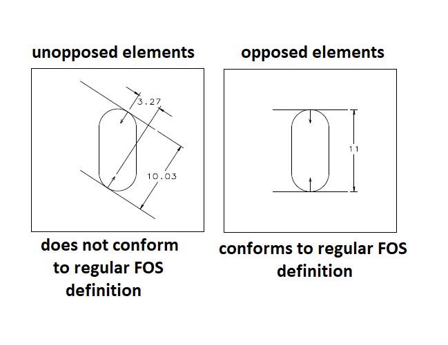
It is not a rule of thumb, it is part of the regular FOS definition:

"1.3.32.1 Regular Feature of Size. regular feature of size: one cylindrical or spherical surface, a circular element, and a set of two opposed parallel elements or
opposed parallel surfaces, each of which is associated with a directly toleranced dimension. See para. 2.2."

Considering the above definition, theoretically, there is a problem with rocking the datum feature simulator to find the minimum separation. Assuming no form error, anything but one condition of the simulator will result in a datum derived from an invalid regular feature of size. See the attached sketch:
opposed-unopposed_kmpgsg.png


With that said, I would never recommend to anyone applying a position control RFS or derive a center plane datum like that. No stability there.
 
As you noted this is only the rFOS definition. This is not a rFOS, its an iFOS(a). Neither datum feature A in Y14.5-2009 fig 4-33 nor any of the options in 4-35 have any directly opposed points/elements and yet are contained by a valid AME.
 
Anyway it matters little how we define it as a rFOS or iFOS. During simulation as a primary datum feature (which we agree is a poor idea) one would have to establish a UAME of minimum separation, not one that coincides with opposed (directly or indirectly) elements. For a feature of this type there is no minimum.
 
chez311 said:
This is not a rFOS, its an iFOS(a)

I think that since the drawing specifies 15+/-0.1 as a size dimension between opposed elements, the feature is a regular feature of size per the definition. Perhaps the transformation from rFOS to iFOS(a) during the attempt to achieve minimum separation does not in itself invalidate the simulation result. I would accept that.

Rwelch9, It should be said if not mentioned before, that the issues discussed here would not occur if the feature was referenced secondary or tertiary, with the rotational DOF that causes instability pre-constrained.
 
Perhaps the transformation from rFOS to iFOS(a) during the attempt to achieve minimum separation does not in itself invalidate the simulation result.

It does not need to be classified in order for us to understand what simulation needs to look like as a primary datum feature. Minimum separation is required.

Y14.5-2009 said:
(b) Primary Datum Feature: Width RMB. The datum is the center plane of the datum feature simulator of the datum feature. The datum feature simulator (or unrelated actual mating envelope) is two parallel planes at minimum separation (for an external feature) or maximum separation (for an internal feature) that makes maximum possible contact with the corresponding surfaces of the datum feature.

It should be said if not mentioned before, that the issues discussed here would not occur if the feature was referenced secondary it tertiary, with the rotational DOF that causes instability pre-constrained.

Rwelch9 - I agree with this statement. Hence why I suggested it could be referenced as secondary in my (16 Jun 20 10:44) comment.
 
Rwelch9,
If you request changes in the drawing, also consider requiring that datum feature B as a continuous feature is replaced by the "MULTIPLE DATUM FEATURES" concept; two mutually centered width-type datum features that establish a single datum center plane, referenced in feature control frames as for example |B-C| (same concept I suggested to you in your other thread recently where it was applied for holes). The reason is that a continuous feature must be inspected for conformance to rule #1 within a single continuous MMC envelope. The external interruptions (the tabs that protrude) will not allow conformance.
 
Unless this was somehow taken care of in the 2018 version of Y14.5.
 
I am of the interpretation there is no requirement that <CF> be used only without protrusions. The standard does not say explicitly one way or the other (though it only includes one type of interruptions in the figures), but it certainly does not forbid it.

 
Status
Not open for further replies.

Part and Inventory Search

Sponsor