Continue to Site

Eng-Tips is the largest engineering community on the Internet

Intelligent Work Forums for Engineering Professionals

  • Congratulations KootK on being selected by the Eng-Tips community for having the most helpful posts in the forums last week. Way to Go!

True Position for hole pattern with just one datum

Status
Not open for further replies.

DawidWas

Mechanical
Dec 29, 2021
2
Hello,

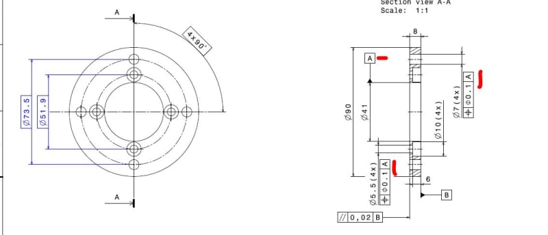
Is it ok, if I use True Position tolerance for hole pattern and use only one datum "A" that is placed on an axis?

These holes are not particularly responsible, they serve only for mounting purposes therefore no perpendicularity to the "B" datum is required really. However, I'm not sure if just one datum is sufficient for that kind of tolerance.

Przechwytywanie_ulatoj.jpg
 
Replies continue below

Recommended for you

Hi,

the axis of datum A would be so short, that it is for sure sane to "fix it" via datum B.

In other words, do |B|A| Datum Reference Frame.

For something else to comment, provide whether your drawing is following ISO or ASME world.

Speaking of which, you might also want to adjust dots and commas for number separation. Either one or the other.
 
Hey, thanks for the reply!

This part is just an example that I found among old files. My question is rather about general principle - does a single datum placed on an axis (provided its length is reasonably large) suffice in similar cases, where I want just to control position of a feature and don't care much about orientation? I'm asking specifically about cases, where I deal with circular pattern of holes on a round part (e.g. flange)
 
DawidWas,

You said you don't care about orientation, but you do likely care about [u,v] ie: rotation about the x and y axes respectively (assuming x and y axes are in plane with B and z is perpendicular to B), just not necessarily orientation/clocking about the z-axis aka [w] rotation. Position tolerance also controls both orientation AND location of each hole axis to within the stated tolerance. This may all be intuitive, but I just wanted to clarify that when you say you don't care about orientation, you are likely only talking about one form of orientation (rotation about the z-axis).

As mentioned above it is important that our datum features are robust for simulation ie: the low length to diameter ratio of A could potentially make it unstable/unreliable as a primary datum feature but we also want to make sure our datum features reflect part function/design intent. You mentioned the example of a flange, which could also be your textbook example - if A is a clearance fit and is secured with a series of bolts the clamping force will tightly pull your surface B in contact with the mating part surface. In this case your datum feature B is likely the best candidate for the primary datum feature as it will constrain your rotation [u,v] and translation [z] in practice, and then A can be specified secondary to constrain [x,y] translation/location.

Your position tolerance can have one datum feature. It can even have no datum features (datumless). Whether or not that "suffices" is up to the designer and what the design intent is.
 
DawidWas,

Think of your datum features as the means with which you will immobilise your part. As cr7 points out, your datum[ ]A feature is short enough that it will not control rotation. The datum[ ]B face should be your primary datum feature.

--
JHG
 
Status
Not open for further replies.

Part and Inventory Search

Sponsor