Eng-Tips is the largest engineering community on the Internet

Intelligent Work Forums for Engineering Professionals

Truss Analysis by hand calculation

Status
Not open for further replies.

jsu0512

Structural
Aug 1, 2017
30
0
0
CA
I'm trying to do hand calculation to check the moment diagram i'm getting from SAP 2000 for the attached diagram.

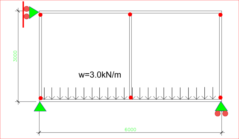
The horizontal beam (top & bottom ) is HSS 6"x3"x1/8" and continues between the support that are 6m distance to each other.

The vertical frames are pin connected between the top and bottom HSS beams.

There is linearly distributed load of 3kN/m along the bottom HSS beam.

Can anyone shed me some light on how to do this with hand calculation?

It would be solvable by hand if there is bracing in each opening but this diagram has no opening.

I want to confirm the moment from SAP result by hand calculation.
 
 https://files.engineering.com/getfile.aspx?folder=2be05a5f-94d7-42ac-a398-9f8b73670ddb&file=Load_Diagram.pdf
Replies continue below

Recommended for you

Assuming the vert members are not pinned at the lower beam member (if pinned, it has no stable vertical support), the load is transferred to the bottom beam and the top beam has no contribution as noted above.

Rather than think climate change and the corona virus as science, think of it as the wrath of God. Feel any better?

-Dik
 
When you indicated you had had enough fun, I thought we were finished, so I went on to other pursuits. If the upper beam is laterally supported, it has vertical support (see below).

Capture_c3qhii.png


BA
 
There you go, changing the system again... there was no roller support at the top left... if you remove it you have what was proposed. Failing that, I would like to introduce a fixed end condition support at the top middle node...

Rather than think climate change and the corona virus as science, think of it as the wrath of God. Feel any better?

-Dik
 
Since you've 90 and 180 degrees angles and equal length of members (assuming 6m was divided into 2) you can use finite element method. I have scribbled a simple format for you to use as your check, maybe later when I have enough time I will try solving it to see the outcome. I didn't complete the equivalent end forces section but it's pretty straight forward, you just have to find the fixed end moments. At node 3, you see two 3KN reactions that's because I have divided the member into 2 and assumed to draw it as two different elements. You can use excel to solve the matrix. Self-weight was ignored.
 
 https://files.engineering.com/getfile.aspx?folder=3c6b517b-eb41-4f42-ab4b-d0190c42f23d&file=FEM_method.pdf
dik said:
There you go, changing the system again... there was no roller support at the top left... if you remove it you have what was proposed. Failing that, I would like to introduce a fixed end condition support at the top middle node...

Yes dik, I have already agreed that the structure is unstable with pins at all joints. I was making it stable by adding a roller support. Your idea of a rigid joint at the top of the middle node is also valid.

BA
 
Since you have the frame analysis results there is no need to solve anything.

Just check that the forces and moments are in equilibrium, that the moments and deflections in the top and bottom chords are consistent with the applied loads, and that the relative deflection of the mid-span top and bottom chords is consistent.

Doug Jenkins
Interactive Design Services
 
Status
Not open for further replies.
Back
Top