Audronic
Mechanical
- Aug 10, 2016
- 3
Good Morning All,
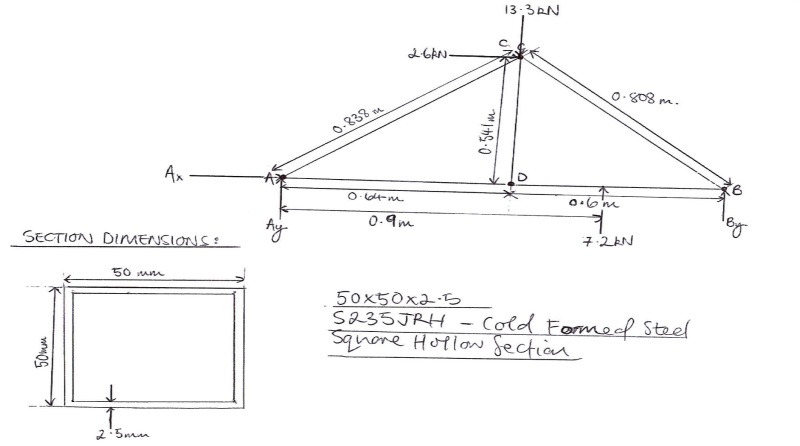
Could someone please shine some light on how I would go about analysing the truss as per the image below? In reality, the truss members are SHS's where every point specified on the diagram is a weld.
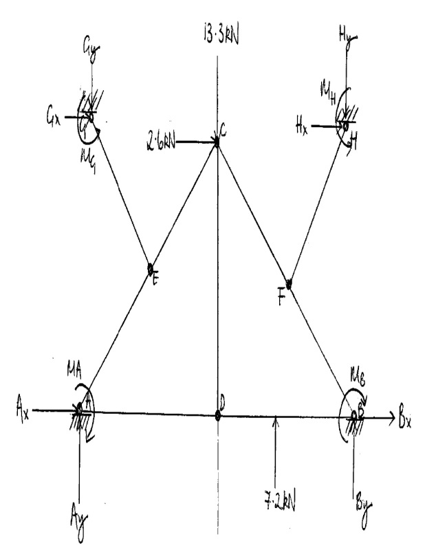
In order to analyse the problem, I was going to assume the following:
-Members EG and FH are zero force members and so can be neglected from the analysis
-The reaction forces and moments acing at supports G and H can be neglected assuming that members EG and EH are zero force members
-The force applied to member BD will cause a compressive for in member CD
-Supports A and B can be changed to a pin and roller support respectively in order to simplify the analysis
Furthermore, once all the forces have been calculated in the truss, am I able to treat all the various members as beams in order to calculate SFD and BMD?
Any help or advice on these matters would be greatly appreciated.
Could someone please shine some light on how I would go about analysing the truss as per the image below? In reality, the truss members are SHS's where every point specified on the diagram is a weld.
In order to analyse the problem, I was going to assume the following:
-Members EG and FH are zero force members and so can be neglected from the analysis
-The reaction forces and moments acing at supports G and H can be neglected assuming that members EG and EH are zero force members
-The force applied to member BD will cause a compressive for in member CD
-Supports A and B can be changed to a pin and roller support respectively in order to simplify the analysis
Furthermore, once all the forces have been calculated in the truss, am I able to treat all the various members as beams in order to calculate SFD and BMD?
Any help or advice on these matters would be greatly appreciated.