Continue to Site

Eng-Tips is the largest engineering community on the Internet

Intelligent Work Forums for Engineering Professionals

  • Congratulations KootK on being selected by the Eng-Tips community for having the most helpful posts in the forums last week. Way to Go!

Truss bearing point at interior? 3

Status
Not open for further replies.

EngStuff

Structural
Jul 1, 2019
81
I want some opinions on this truss. It's an existing residential cathedral truss that spans only 30 feet. I am 99% sure that the reactions are on the outsides only, especially 30 feet isn't that long for a truss to span to both of its ends. The part I am unsure of is because of a vertical web that runs straight to an interior wall. That being said, just because it has a vertical web on top of a wall, doesn't mean it is a bearing point. I have designed trusses that have similar configurations with 2 bearing points on its ends only, but I have also designed similar configurations with 3 bearing points with one in the interior. Not saying I am a pro when it comes to designing trusses, but enough times to have an idea of what can or can't be done, but not enough times to not get stumped on this situation. Though I still think it's not load bearing. There is no gap, but I've seen many times that contractors don't leave gaps between truss bottom chords and top of plate members for partition walls. Also, maybe they did leave a gap, but as years went by, it sagged to the point that it's bearing on the wall, but not enough to cause any structural or serviceability issues. I did not see any "crushing" on the top plate (didn't check all locations).

What I unfortunately can't check is if the wall is sitting on a beam or joists below it. If it's on joists that are 2+ feet away from the support, then I would ultimately assume not load bearing. If the wall was on a beam, i would still be unsure at that point. Until we get a chance to go into the crawl space (have to create a hole somewhere which adds more time and cost, and would like to try figuring it out before we go that route)
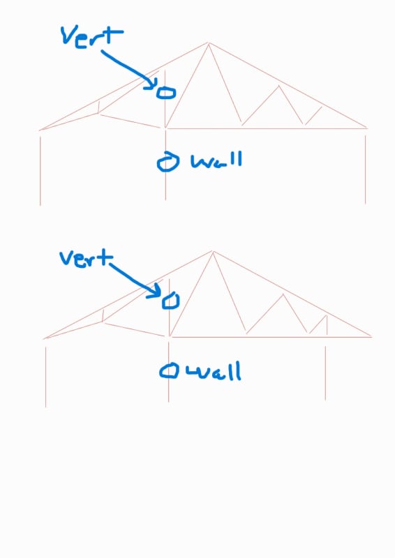
Truss_paquvw.jpg
 
Replies continue below

Recommended for you

Also, regarding material strengths, I have seen higher grade lumber being used in trusses, specifically as chord members. So it wouldn't be out of the realm of possiblity that you have Select Structural lumber as the chords, but the only way to confirm that would be to find either the original truss design sheets, or a grading stamp on the lumber.
 
EngStuff, I wonder what kind of analysis you're using? Pin joint modeling has not been used for ~20 years in the truss industry.

If you have a contact at a local truss plant they might run a tentative design for you. That might give you more information.

If not, you can email me at rsitruss at yahoo dot com and I'll see what I can come up with. I'll be back in the office on Thursday. I may not be able to give you an absolute answer, but might be able to give you something helpful.


Abut the wall being about 32" away from a beam in the crawlspace - No way in HELL would I use that for bearing unless I knew for a fact that the floor joists were designed for that situation.
 
phamENG said:
Assuming it's southern pine, anyway
jayrod12 said:
regarding material strengths

This is one big issue on our end, it's way to difficult to determine what the material is, so we assumed SPF #2, there was no stamp of any sort to determine the lumber. It's a typical residential home in Michigan.

RontheRedneck said:
EngStuff, I wonder what kind of analysis you're using? Pin joint modeling has not been used for ~20 years in the truss industry.

It is that method that we are using. Haha. However, any new designs, we only pin the webs, chords are continuous. When we check old existing trusses, we pin the joint's because they always end up failing when we check continuous top and bottom chords.


Looks to me like the wall is bearing (since you asked).
17.5 PSF - must be SOUTHERN Michigan. (Certainly not northern)

I assume the object here is so you can remove a part of the wall??
If a dropped beam is not desired, MAYBE they can fish one up along side the vertical and make the connection that way.
Might want to use a THA style hanger.
Then you just need to get the reactions back across that 32" offset in the crawl space. Sounds like a couple of extra floor joists could be added (maybe LVL material).
I guess if it was easy... they wouldn't need us!

 
Engstuff, I doubt the wall was intended to be load bearing if it is offset 32" from the floor girder below. That being said, I suppose that the truss designer may have seen the wall on the plans and assumed it could be used as load bearing for design of the trusses, without consideration of how the wall was supported at the level below. I would like to think that truss designers would be more thoughtful than this, but I don't really know.

I suspect that one of the reasons the truss is failing in your analysis is because you are using SYP #2 for the chords. It is very common for truss designers/manufacturers to use higher grade lumber where it is needed (usually the chords). However, without documentation of the lumber grade, I would be hesitant to assume greater than #2, so I guess you are right to be conservative in that regard. What happens if you do your analysis with select structural material?
 
I would have a local truss company run the truss through their analysis and design program. I would think that they would be able to produce a more accurate evaluation of the existing truss then an EOR running through a regular software package.

I would also consider running the loads on the floor beam and perhaps the joists. This should be simple enough. Run it two ways, one with roof loads via the wall, another without the roof loads. If the joists and beam fails with roof load then you have another indication. If the joists and beam can support the roof load, then I would consider the results inconclusive.

 
I am still curious about the scope of this project - remove the wall to open up space, or to modify/strengthen the existing truss?
 
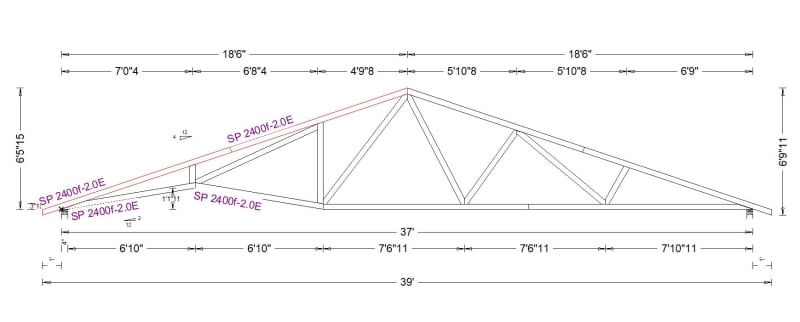
Just for the heck of it I ran a 37' truss and did my best to make it similar to what's been described. Here's what I came up with:

37_foot_cath_truss_xml6wh.jpg


I used 30-10-10 loading. I'm in central Illinois, and that's what we use in the Chicago area. I believe Michigan was mentioned as the location for the existing truss. I don't know the loading requirements for that area, so I'm just guessing.

On the left side of the truss where you see "SP 2400"-2.0E, that indicated MSR 2400 SYP lumber. That's the best grade we carry. That may or may not be the lumber that's in the existing truss.

The TC on the left side failed. Going from memory, the CSI was 1.5 or a bit more. Which means the truss does not work. And it's not particularly close to working.


This is of course not an exact representation of the existing truss. But I'm hoping it gives the OP some more info to work with.
 
RontheRedneck, nice work, but I think the OP’s truss is 30 feet, not 37, right?
 
gte447f, back on May 2nd his attachment indicated a 37' truss. So that's what I went with.
 
Yeah, it woulda been nice if the OP noted in his post that it was actually 37 ft - not 30 ft.
That is a huge difference and would have def. tempered my responses.
 
RontheRedneck, thanks for the clarification. I see now, in his attachment, where the OP says "Truss spans about 37 feet...(I was wrong about 30 feet)". That's a significant difference!
 
@RontheRedneck: thanks for running the truss for us. For some time, we've lacked a member with access to the software that would allow us to explore stuff like this in detail.
 
when there is an interior bearing wall along the bottom of the trusses, the trusses would consider a frame action including the trusses and the perpendicular bearing wall below?

disclaimer: the answer is not taken to be correct unless approved by a senior engineer.
 
mronlinetutor: I'm not sure what question you're trying to ask?

RontheRedneck - very nice. You mention you've been designing trusses since the 80s; are you still working for a fabricator or do you just happen to have some nice TPI-1 based software at your disposal? If the later, where did you manage to find it?
 
Complaint - the OP has not stated what he was tasked to do thus far.
 
phamENG - I'm still working for a truss fabricator. It's what I've done most of my adult life. Although I'm a farmer too, which explains the screen name.


stanleyshum1997 said: "When there is an interior bearing wall along the bottom of the trusses, the trusses would consider a frame action including the trusses and the perpendicular bearing wall below?"

I don't understand what you're saying. In truss design, a bearing is a bearing. Aside from the pin/roller thing, there are not different types of bearings.
 
Thanks all, this was a lot of help.

I do want to apologies, I tried to edit the first post, but it looks like at a certain time period they don't allow the original posts to be edited. I wanted to make the changes and add the link there too.

Also, to clarify, the intent was to remove the wall below the vertical web.

I think essentially our original thought was correct, it was not supposed to be a load bearing wall but ended up becoming one. Seems like it was more likely during the truss design phase.

We will end up designing a beam for this. Considering the floor was not sagging at the existing wall. perhaps the wall is not taking all the load, but enough to support the truss. we might go with one of the two options.

Option 1. place a pin and design for the full load on the pin.
Option 2. add a spring, see at what point the truss is close to failing, and to design a beam using the vertical load from that.

We might just end up going with option 1.

we will also have to design for a new beam at the first floor and take the load to the existing wall and beam. analyze existing too.

RontheRedneck - Thank you! Much appreciated for that. I also changed the lumber strength to match yours and was getting the same failure at those two.

The program you guys use. so, they pin the webs and have continuous top and bottom chords? I assume in this specific truss; you also have to pin the bottom chord at the cathedral?

When we have clients that want a truss design. First, we always try to send them to a truss manufacture and explain why that is the best route. There are some cases where the client has a way of attaining the materials and building up their own trusses for a lot cheaper. At that point, we design the trusses using pinned webs and continuous chords. However, we use ply/osb for gusset plates.


HouseBoy said:
Looks to me like the wall is bearing (since you asked).
17.5 PSF - must be SOUTHERN Michigan. (Certainly not northern)

I assume the object here is so you can remove a part of the wall??
If a dropped beam is not desired, MAYBE they can fish one up alongside the vertical and make the connection that way.

Correct, Southern Michigan. I like the idea of placing a beam within the verticals and using a THA hanger. We will consider taking a closer look at this. Probably also nail the beam into the verticals for stability or we might just design the beam using a full unbraced length.
 
Now, it is clear, that you shall run two models, one with the wall as a support, and one without. If it is failing without the wall, then you have no choice but to strengthen the truss or add another beam to share or relieve the load that gets to it. I think several people here already have good ideas.
 
When you have an interior support inside the bottom of a trusses, the trusses is not no longer consider as a trusses. The trusses becomes a frame and you no longer have the triangular stability a trusses promised. In other words, the trusses is unstable? In other words, you have to design the structure as a frame and you no longer can have all pinned joints.

So you have to leave room between the trusses and the interior wall. But then the interior wall does not have the diaphragm action the roof promised. One way to include the diagram action is to elevate the trusses at both ends of the trusses.

But then, the trusses is still have a problem on the left hand side because the trusses has a kink on the bottom cord. A horizontal member is missing. You cannot have a kink either unless you design it as a frame again?

The trusses is considered as a frame made of steel with moment joints. Strength the frame by welding a uniform plate on one side of the frame. Provide lateral bracing on bottom of the frame to avoid out of plane action. Do not weld two plates as a single plate at the kinks vertical location. To have even better result is to provide a plate on bother sides of the frame. The frame is welded while the plates are bolted on. The plate has to considered as plate and not a shell or membrane because of bending moment out of plane at the kinks vertical location. In fact, there are two vertical bending locations. The location is at the kinks vertical and interior wall vertical.

Since you have to provide crawl space, you have to eliminate the plate. But then the trusses have to design for lateral out of plane bending. The plates are just to demonstrate the thought processes.

Disclaimer:. The proposed solution cannot be adopted unless sealed by senior engineer.
 
Status
Not open for further replies.

Part and Inventory Search

Sponsor