Continue to Site

Eng-Tips is the largest engineering community on the Internet

Intelligent Work Forums for Engineering Professionals

  • Congratulations KootK on being selected by the Eng-Tips community for having the most helpful posts in the forums last week. Way to Go!

Truss chords and EN 1993-1-8. 1

Status
Not open for further replies.

trazimcalvina

Mechanical
Nov 20, 2020
10
Hi all,

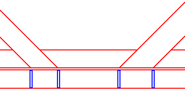
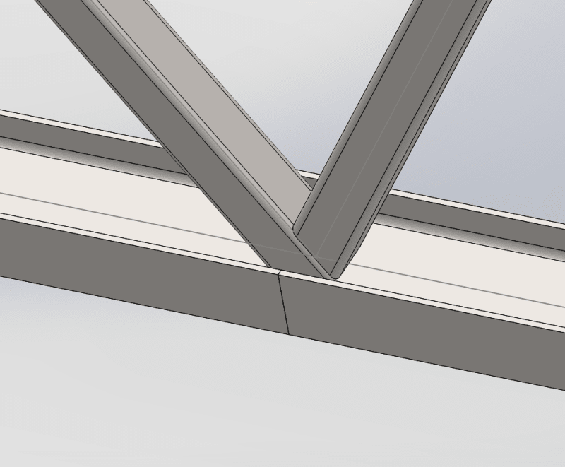
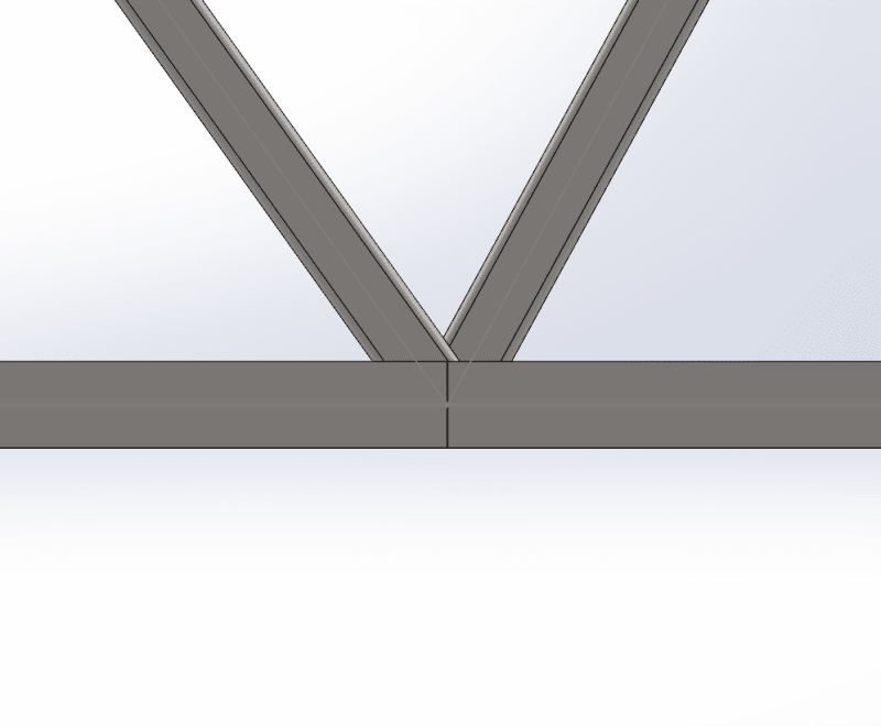
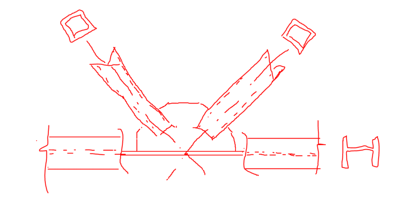
I am currently designing a truss with IPE 140 (I-beam) as chords. The beam however is rotated on its side, meaning its web is horizontal. The truss will have square hollow structural steel diagonals which are welded onto the horizontal web.
While checking those diagonals in the Eurocode EN 1993-1-8 I realized they only offer formulas for the case where the beam in the chord is vertical! (see attached). I tried scouring the rest of the standard and some additional literature but I could not find a word about my case.
My colleague suggested using all the dimensions from my horizontal web case and inserting them into the formulas meant for a vertical case (this means essentially switching around the height and width of the beam as well as changing its thickness) and the joint passed!
But I am of course not comfortable with this, nor am I sure that this is correct.

Has anyone met with this before? What was your solution.
 
 https://files.engineering.com/getfile.aspx?folder=75883c29-d9cf-491d-838b-a1dc687e028e&file=Beam_vertical.PNG
Replies continue below

Recommended for you

1) depending on how you detail the joints, you may well have to accept that your web joints will not be concentric with your chords here.

2) I would consider using provisions meant for RHS chords here since, in many respects, that will more accurately capture the condition where your webs meet your chords.
 
Can you show us a sketch of how you intend to detail the joint?
 
Actually, Part 9 of the AISC Steel Construction Manual (15th edition), has the yield line formulas you need for dumping large loads into a WF web.

Lacking better analysis, can I suggest adding stiffeners as able?
WF_Web_Stiff_mbyuiq.png
 
Apologies for the late reply, busy weekend.

@KootK
1) Yeah since I was planning on gap joints I was expecting some eccentricity and was planning to take into account the resulting moments.
I planned to simply add this to the axial forces per formula 7.5 below.

2) Why do you think my conditions warrant a switch to the RHS provisions, I understand its probably a more conservative
solution and therefore a good idea, but is there any deeper reason that I am not seeing?

3) This is the current solution(no more gap in the joint and no more eccentricity), but I am still not really sure whether it wont change to a gap design.
Joint_sketch_1_mkxtpx.png

Joint_sketch_2_sap70m.png


@winelandv

Thanks for the suggestion, but do these stiffeners make sense with the sketch of the joint I attached?
 
OP said:
Why do you think my conditions warrant a switch to the RHS provisions, I understand its probably a more conservative solution and therefore a good idea, but is there any deeper reason that I am not seeing?

In my opinion, the RHS provisions will be perfect for this situation because, if you use the correct provisions:

1) They are intended for trusses and;

2) They are intended for loads coming in through HSS members and;

3) They are intended for plates stiffened on two sides and loaded transversely. And that's exactly what this is.

As I see it, nothing meaningful is sacrificed iby using the HSS provisions here because they are not, explicitly, wide flange provisions.

I feel that using the HSS provisions should be considered "optimal and appropriate" rather than "more conservative".

winelandv said:
Thanks for the suggestion, but do these stiffeners make sense with the sketch of the joint I attached?

Absolutely. The stiffeners are an excellent suggestion if they would not be economically objectionable. I should have proposed them myself. It's always better to move connection loads around via plate in plane forces rather than plate transverse bending.

 
Is there any chance that your webs could be wide flange members of the same. nominal depth as the chords?
 
This is potentially a pretty strong setup too. You'd have to consider weld access etc though.

C01_box_wkjsrt.png
 
trazimcalvina (Mechanical) said:
do these stiffeners make sense with the sketch of the joint I attached?

The answer is maybe - it depends on what the capacity of your WF web is to resist the forces that your gapped or overlapped K-connection will impart to it. In lieu of an explicit analysis of the web, a stiffener (or even 2), might be a bit of an adder to the fab cost, but it's also cheap "sleep well at night" insurance for the designer. It's cheap in the sense that fab cost of the stiffeners pales in comparison to the whole thing falling down. :)

I agree with Koot, however. I would apply the RHS provisions should cover to this, because it's essentially the same situation.
 
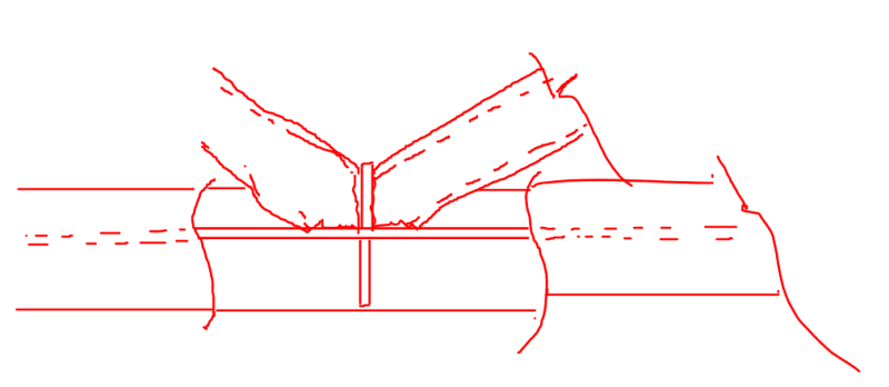
Let's say that someone came to me with only the following constraints on this and wanted to know my recommendation for the connection:

1) HSS webs.

2) WF on the flat chords.

My recommendation would probably be the detail shown below.

C01_box_fgb1u6.png
 
A belated thank you to you all for providing a lot of useful information!
 
A horizontal I-Beam rotated in this fashion is a trap for water, dust and dirt. Hardly ideal. If this is outside and expose to the weather I'd consider it a non starter.
 
Status
Not open for further replies.

Part and Inventory Search

Sponsor