Continue to Site

Eng-Tips is the largest engineering community on the Internet

Intelligent Work Forums for Engineering Professionals

  • Congratulations KootK on being selected by the Eng-Tips community for having the most helpful posts in the forums last week. Way to Go!

Truss Cut 1

dgengineering

Structural
Jul 24, 2023
29
Hi everyone,

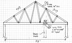
I have a remodeling project and it's under construction now. The builders cut the existing truss bottom chord to place a 21' span beam where the wall used to be. The inspector wants approval for this.
The beam was designed for ceiling loads since the architectural plans didn't show trusses. How do I determine if the truss cut will add more load to the beam or not. Also, how much load should I use to check the beam strength again. See my sketch

Thanks
 

Attachments

  • truss cut sketch1.pdf
    61.7 KB · Views: 81
Replies continue below

Recommended for you

Before you get to sorting the beam, you need a plan to sort the truss which is badly compromised.. It seems to me e that it would be simplest to get rid of the beam and repair the truss bottom chord.
 
The truss BC is in tension. Since it appears they cut the BC and did not repair the truss, it's been significantly compromised. No way is it O.K. as it is.

I'm with KootK in thinking it would be best to lose the beam and repair the trusses.

If the building is relatively new you might possibly be able to find who manufactured the trusses and get design info from them. They may or may not be able to produce a repair drawing. If not, you're pretty much on your own.
 
I agree that the existing trusses haves been seriously compromised by cutting the bottom chords to accommodate a 21' long beam. There may be ten or eleven trusses involved as truss spacing is 24 inches.

Tension capacity in the bottom chords must be restored by providing tension straps at each cut. Temporary shoring should be provided to protect workers from collapse during remedial work.

In future, avoid cutting structural members without engineering approval...duh!
 
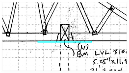
Considering the current situation, the simplest solution seems to be adding Simpson straps to the bottom of the truss to lift the bottom chord. After a quick calculation, I found that your 5.25" x 11.875" x 21' LVL will not be able to effectively support the vertical load. In the worst case, the tension force would be at least 2700 lbs.1733738126756.png
 
In case anyone else is annoyed at having to download a PDF, here is OPs sketch:
1733756500254.png
 
After a quick calculation, I found that your 5.25" x 11.875" x 21' LVL will not be able to effectively support the vertical load
This is not the question being asked by OP, but I tend to agree. Even under the most minimal load that I can imagine acting on the trusses, the beam seems a bit under-designed. Perhaps, deflection is not a concern here?

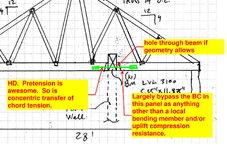
In terms of a solution, if you can resist the vertical reaction from each side of the cut truss as well as the bottom chord tension force, I'd tend to think that may be acceptable. I would consider a tension connection that can be pretensioned, like a shear wall hold-down or deck tension tie with a threaded rod connecting both sides of the bottom chord. I feel that a flat strap could have some slack and be more likely to deform under load, leading to excessive vertical deflection (again, if that's a concern). In terms of the tension force, that can either be found from an FBD or you could alternatively determine the maximum tension capacity of the bottom chord and base it on that (although that could be overly conservative).
 
In case anyone else is annoyed at having to download a PDF, here is OPs sketch:

I definitely prefer it as you've done it. So thank you. That said, I celebrate OP for the following:

1) Posting a sketch via any mechanism. Many folks don't.

2) Posting a rather excellent engineering sketch in my opinion.
 
Even under the most minimal load that I can imagine acting on the trusses, the beam seems a bit under-designed. Perhaps, deflection is not a concern here?
OP mentioned celling loads at the top. I'm guessing that the intent here was never to resist any roof loads with the new beam. Maybe just originally conceived as an interiors renovation of sorts.
 
Looks good! Pretension through the beam each side of bottom chord is the best solution.
 
KootK, thanks for the sketch showing the tension connection. That's exactly what I had in mind.
OP mentioned celling loads at the top. I'm guessing that the intent here was never to resist any roof loads with the new beam. Maybe just originally conceived as an interiors renovation of sorts.
The beam was designed for ceiling loads since the architectural plans didn't show trusses.
Ok, my bad. I failed to read this correctly. If somehow the beam is only needed to resist ceiling loads, then forget what I wrote above about the beam appearing to be inadequate. With that said, I'm not sure this is necessarily true. Is it really possible that the beam will not be supporting roof loads?

I also wonder if the removed wall was intended to be load bearing. It seems like an odd location for a LB wall considering it doesn't coincide with a truss panel point.
 
With that said, I'm not sure this is necessarily true. Is it really possible that the beam will not be supporting roof loads?

Not in the true condition. Just in the condition that OP assumed when she designed the beam. One of the reasons that I would be inclined to get rid of the the beam entirely is deflection compatibility. Near the beam ends, the beam will attempt to support the trusses. And that will carry down through the load path, whatever that is.

In the middle of the beam, the trusses will likely be supporting the beam. In which case the hangers will have been installed upside down. There's a fair bit of complexity and uncertainty with that beam in play.

If this was my building, I'd have the trusses shored, the bottom chord sister-ed back to health, and that beam disappeared. Obviously, the trusses can support the ceiling and always could. You know, prior to being violated horribly.

I also wonder if the removed wall was intended to be load bearing.

I would guess not.
 
To me, it's almost looking like the builders removed a wall which they thought was needed to support the trusses, then proceeded to cut the bottom chords of perfectly good trusses, and finally added a beam which isn't needed! Yikes!
 
My impression is that it was assumed that the framing system was not trusses but something like rafters & ridge beam for the roof and joists of some kind for the ceiling. Ergo the joists might have been supported by the interior wall without that wall picking up any ostensible roof load. A truss bottom chord is not going to look like a very long span capable member if one doesn't recognize that it's supported by the truss panel points.
since the architectural plans didn't show trusses.
 
Thank you everyone for your help.

One more question. If they drill a hole in the beam for the threaded rod, it weakens the beam, right? It's gonna be in the tension zone.

The truss bottom chord is 2x4 so let's say they use MST straps it's wider than 2x4 members. My solution is to sister the 2x4 with another 2x, bolt it to the BC and put MST straps from top and bottom. What do you think?

My impression is that it was assumed that the framing system was not trusses but something like rafters & ridge beam for the roof and joists of some kind for the ceiling. Ergo the joists might have been supported by the interior wall without that wall picking up any ostensible roof load. A truss bottom chord is not going to look like a very long span capable member if one doesn't recognize that it's supported by the truss panel points.
yes the trusses weren't shown on the architectural plans so it was assumed there were only ceiling joists
 
If they drill a hole in the beam for the threaded rod, it weakens the beam, right?
Yes, but I think it would be rather insignificant. You could calculate the section properties with the hole accounted for. This would likely be conservative since the holes are presumably only every 24", as opposed to a slice removed for the full beam length. Despite this, I think you would still likely only see a minor impact on strength.
 
If the trusses are made whole, it is more likely that the beam will be supported by the 10 or 11 bottom chords, because the trusses spanning 28' are stiffer than the beam spanning 21'. So the trusses will likely pick up the ceiling load via the beam which is a continuous member spanning only two feet between trusses. The hole in the beam will not be a problem provided the trusses are capable of carrying the ceiling load. We don't know the size of the bottom chord of the trusses, but if necessary, you can beef them up between panel points each side of the cut.
 

Part and Inventory Search

Sponsor