Continue to Site

Eng-Tips is the largest engineering community on the Internet

Intelligent Work Forums for Engineering Professionals

  • Congratulations KootK on being selected by the Eng-Tips community for having the most helpful posts in the forums last week. Way to Go!

Truss end reactions

Status
Not open for further replies.

StrEng007

Structural
Aug 22, 2014
506
Say you have a single-story masonry structure with bond beams and wood trusses with an overhang. For lateral wind, most engineers would agree the wall is braced at the top by the trusses that bear over them (axial load into the end of the truss), which will "push" that load into the diaphragm. In this situation, each end of the truss is assumed to be "pinned" to the wall below due to wind acting in either direction.

Trusses are typically designed to accommodate some horizontal displacement at one end. When this displacement is restricted (as mentioned above), a large horizontal thrusting reaction may develop on each side.

I don't see many engineers accounting for these horizontal reactions, yet we're requiring that trusses be pinned on each end. Are most engineers ignoring this?

 
Replies continue below

Recommended for you

A truss with overhangs at each end is really no different than a beam with overhangs. Neither the displacement of a beam or a truss is restricted by design assumptions. In both cases, we assume hinge at one end and roller at the other. In both cases, they brace the top of wall, provided the diaphragm is adequately connected. But the walls deflect when the wind blows. The magnitude of deflection is dependent on the rigidity of the diaphragm.
Edit: To a lesser extent, deflection of the wall is dependent on the rigidity of the wall. That is normally neglected by engineers.

BA
 
Veering off topic slightly, although still related, as mentioned the lateral load has to travel through the truss web members to get to the roof diaphragm. Does anyone supply this force to the wood truss engineer so they can design their trusses accordingly, or do we assume this force is so small compared to the capacity of the web members?
 
The wind force should be specified in the drawings because it affects member forces. As you say, it's pretty small, particularly when trusses are spaced at 24", so it may not be specified. Also, trusses cannot be resisting maximum wind and snow loads simultaneously.

BA
 
To OP's point, I think many engineers handwave the required horizontal displacement away as small (which may or may not be true, depending on the truss), and easily accommodated by connection slip and wall flexibility (which again, may or may not be true).

Standard trusses and light frame walls? Probably works.

Scissor trusses and masonry walls (or near wall returns)? The case isn't so clear.

----
just call me Lo.
 
BAretired,
The overhang statement was irrelevant. I'm considering a single-span truss with (2) bearing points.
You mentioned that both ends of the truss will brace the top of the wall. How do you figure the end with the roller braces the top of the wall?

Lo,
I figure you're referring to light-frame walls regarding the overall flexibility of the system. In that case, we knowingly pin trusses on each side and hope the system deflects enough to alleviate that horizontal displacement? And if it doesn't? What about flat trusses at bond beams with embedded truss straps?

I realize that we encounter this situation more often with scissor trusses and arch-type trusses. However, both trusses with sloped and flat top chords are also modeled to allow horizontal displacement.

 
StrEng007 said:
BAretired,
The overhang statement was irrelevant. I'm considering a single-span truss with (2) bearing points.
You mentioned that both ends of the truss will brace the top of the wall. How do you figure the end with the roller braces the top of the wall?

Why shouldn't it? It is not a true roller, capable of rolling away forever. It is a design device needed to make each truss statically determinate. Same as a beam.

The beam or truss limits the spread of the walls.


BA
 
StrEngoo7 said:
I figure you're referring to light-frame walls regarding the overall flexibility of the system. In that case, we knowingly pin trusses on each side and hope the system deflects enough to alleviate that horizontal displacement? And if it doesn't? What about flat trusses at bond beams with embedded truss straps?

We don't hope the system deflects enough to alleviate the horizontal displacement. If it doesn't, our design is conservative.

BA
 
In reality, the top of the wall at both ends of the truss moves outward slightly under gravity loads. We model this as pinned at one support, and a roller at the other support. It does not mean the wall cannot impart lateral load to the trusses and diaphragm--it is just how we model the truss for its design.

DaveAtkins
 
BAretired said:
We don't hope the system deflects enough to alleviate the horizontal displacement. If it doesn't, our design is conservative.
I agree with you, the design of the TRUSS is conservative if it is truly pinned and incapable of moving on each end. A conservative wall top plate or tie-beam design would consider an additional horizontal load.

BAretired said:
It is not a true roller, capable of rolling away forever.
Very good point. At some point, the connection has to engage. It's a belt and suspenders situation.


DaveAtkins said:
It does not mean the wall cannot impart lateral load to the trusses and diaphragm
I agree the wall can impart load to the truss. I'm more concerned with the truss imparting load to the wall.

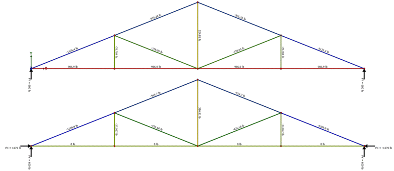
As an illustration, here are the DL reactions from a 30FT truss, 2FT o.c., 20 PSF. The second model (pin-pin) yields 1070 LB/truss of outward force = +500 lb/ft down the support line. Where does this theoretical load go? Again, belt and suspenders?

Truss_dxj10r.gif


I appreciate your feedback and agree with you overall. I realize that most of us don't load our structures with this displacement load. I was hoping to categorize this as a black & white thing and put it to rest. This discussion is to get your opinion. Thank you all.
 
StrEng007 said:
Where does this theoretical load go?

The key to this is not to focus on the load but, rather, to consider the axial elongation of the truss bottom chord and use that as a barometer as to whether or not you feel that you really have a problem worthy of explicit consideration. As Dave mentioned, take the bottom chord elongation, divide it by two, and that's how much the tops of your walls would need to be able to move in order to NOT generate the load that concerns you under extreme loading. In a flat bottom chord truss, that movement estimate ought to be fairly small.
 
Thank you, KootK

I'm usually specifying loads imposed for the truss designer. I haven't seen anything in typical wood truss shops or the SJI design tables (see note below) to anticipate this elongation. As the EOR for the structure, where can I find information regarding these values (if available)? I've only come across disclaimers for truss systems that have an intentional arch or scissor trusses.

Note: This discussion originally came up during a conversation of long span joists and joist girders. I wanted to bring this topic back to a classic wood truss example. The topic related to the fact that long-span trusses will develop a parabolic/catenary load that is often ignored.
 
StrEng007 said:
As the EOR for the structure, where can I find information regarding these values (if available)?

You can estimate it yourself. For either a steel joist or a wood truss, it's a pretty easy thing to:

1) Estimate the bottom chord tension.

2) Make a conservative guess as to the axial stiffness of a probable bottom chord (L2x2 or 2x4).

3) Estimate elongation.

Alternately, you can use a truss model like the one that you posted above to estimate the anticipated movement.

I'd not intended the suggestion to be something that you'd necessarily do on every project but, rather, an exercise that you might do once or twice to convince yourself that this is not a reason for concern in many practical situations.

For what it's worth, I was wood truss designer before and during college. I don't once recall anybody specifying wall loads to be resisted by the trusses. And that may have been a real oversight in some situations. That said, there are mitigating factors, some of which have been mentioned previously:

1) Any tension added to the bottom chord should be dwarfed by natural truss bottom chord tension capacity.

2) Any compression added to the bottom chord may have to overcome natural truss bottom chord tension before posing a problem.

3) Any applied compression will make it's way into the top chord as well as the bottom chord. And the top chord is better braced.

4) Where applied compression makes it's way into the bottom chord, often the bottom chord will already have some bracing for uplift design.


KootK said:
3) Any applied compression will make it's way into the top chord as well as the bottom chord. And the top chord is better braced.

4) Where applied compression makes it's way into the bottom chord, often the bottom chord will already have some bracing for uplift design.

I'm not so sure I agree with 3) above, assuming all joints are hinged and the bottom chord is flat. A horizontal load applied to each end of a flat bottom chord affects only the bottom chord; no other truss member is affected.

If a flat-bottom truss is connected by a pin to an infinitely rigid foundation at each end, gravity load will not cause a problem, but a temperature increase may cause buckling. One end connection should permit sufficient horizontal movement to allow free expansion of the truss.

BA
 
KootK,
I think the wall loads end up in the top chord of each truss (ignoring any ceiling action at the bottom chord). Recall our previous discussion regarding the fasteners of a pitched roof, and how those anchors impart a drag to each truss?

What did the truss designers assume would brace the top of the wall? Or was the wall below of no concern?


I would apply an horizontal spring rather than full support. The question would then be what its stiffness is. This could be determined considering the friction at the support under the vertical load (reaction).
 
The truss designers assume whatever makes their life easier. They only care about the trusses themselves, don't really care for much else. No money or time to worry about the things that are outside their scope.

I feel that many people want to dig too deep on this stuff. Top of the walls are braced by the ceiling/roof structure. To consider the truss analysis correct, there just needs to be enough flexibility in the top of the walls to allow for some horizontal spread of the walls to mimic a roller support. In many cases, this is a non-issue. In some rare situations this can cause a large issue.
 
BAretired said:
I'm not so sure I agree with 3) above, assuming all joints are hinged and the bottom chord is flat. A horizontal load applied to each end of a flat bottom chord affects only the bottom chord; no other truss member is affected.

Not so my friend. Model up a common truss, apply a horizontal load to the bearings, and watch that load spread throughout the truss according to stiffness.
It's analogous to saying that an axial load applied to the bottom flange of a steel beam never makes its way to the top flange. The shear transfer is just less efficient in a truss and you'll have upward flex in the mix.

engineering_patrol said:
I would apply an horizontal spring rather than full support. The question would then be what its stiffness is.

I agree that the true behavior of the thing will a pin with a stiffness that is difficult to define. In many buildings, that will also be complicated by the fact that the spring stiffness will vary with proximity to wall corners.
 
StrEng007 said:
I think the wall loads end up in the top chord of each truss (ignoring any ceiling action at the bottom chord). Recall our previous discussion regarding the fasteners of a pitched roof, and how those anchors impart a drag to each truss?

This depends on whether we're talking about:

1) A set of balanced wall loads resulting in a truss that is in equilibrium without diaphragm action. In this case, I'd expect the loads to remain within the truss, mostly the bottom chords when flat OR;

2) An unbalanced set of wall loads in which the imbalance alone will make its way into whatever diaphragm system(s) are available and over to the shear walls. In this case, yes, the story that we tell regarding the chord forces has to jive with the story that we tell regarding drag strut behavior.

StrEng007 said:
What did the truss designers assume would brace the top of the wall? Or was the wall below of no concern?

They assumed that the trusses braced the walls of course. Truss designers tend to be rather pragmatic folk, much like carpenters. But no, your average truss designer is not losing any sleep over whether or not wind loads on walls are likely to pancake sheathed roof systems wholesale.
 
KootK said:
Not so my friend. Model up a common truss, apply a horizontal load to the bearings, and watch that load spread throughout the truss according to stiffness.
It's analogous to saying that an axial load applied to the bottom flange of a steel beam never makes its way to the top flange. The shear transfer is just less efficient in a truss and you'll have upward flex in the mix.

You have me thinking now, KootK. With a beam, I agree that the load is eccentric, so there is a constant bending moment which stresses other parts of the beam, not just the bottom flange. But with the truss shown here, by the method of joints, no member other than the bottom chord can be stressed when a horizontal load is applied to each end of the truss.

For example, the bottom half of the top chord cannot have stress in it as it would imply a shear in the bottom chord which cannot exist. Similarly, members other than the bottom chord cannot be stressed, using standard methods for solving trusses. With a 10# load applied at each end, all members have 0 stress except the bottom chord which has 10# force in every panel.

image_d2mexc.png


BA
 
Status
Not open for further replies.

Part and Inventory Search

Sponsor