Continue to Site

Eng-Tips is the largest engineering community on the Internet

Intelligent Work Forums for Engineering Professionals

  • Congratulations waross on being selected by the Eng-Tips community for having the most helpful posts in the forums last week. Way to Go!

Truss Members Continuity Modeling in Structural Design Software 3

Status
Not open for further replies.

M.IDR

Structural
Dec 31, 2020
42
Hello Engineers,
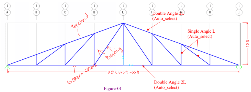
Modeling of Truss members as shown in Figure-01 have bending moments from analysis when the bottom chord is considered Continuous. As the truss members are usually pin joints, but due to continuity, the top and bottom chord are not considered to be pin with adjacent members as shown in Figure-02. So do you think it should be considered pinned while analyzing it as shown in the figure-03? or Figure-02 is Correct?​

image_tehiht.png

image_coflmo.png

image_mdkp6k.png
 
Replies continue below

Recommended for you

How does your loading look like? Only at the nodes?
 
@SteynvW Yes Exactly all loads are applied at Nodes only, Only Wind Loads applied shown in the figure below.
image_s4nady.png

Moment diagrams of members are shown.
image_yiuhma.png

If the Members are only Designed based on the Axial Forces then the sections are light/economical, while bending moments involvements make the designed sections Heavier?
 
Personally, I do it closer to figure 2 than figure 3 because that's how most trusses are built in my experience.... With pinned connections to all the web members, but continuous from support to support.

One difference, however, is that I would model one of the chord ends with a moment release wherever they meet at a support or at the apex point.
 
I agree with Josh. It should be modeled the way it will be constructed. If the chords are going to be continuous when it's built, make them continuous in your analysis. But the joint form the web to the chord should generally be a pin as long as the web members are relatively small and/or the connections don't allow for much moment transfer. If the chords and webs are roughly equal in section properties and you do a CJP weld, I'd expect it to transfer moment.
 
1) If this is new design and gravity load dominates, consider flipping your diagonals for greater efficiency. It's handy to have your diagonals in tension as they tend to have the longest unbraced lengths.

2) I also prefer model #2:

a) Same reasons as the other guys.

b) Nowadays, #2 really doesn't require much additional effort.

c) In rare cases, some combinations of truss shear flexibility and individual chord stiffness will result in an unspliced bottom chord behaving a bit like a beam between supports. Model #3 doesn't capture that.

3) A nice, deep truss like this with the loads at the panel points is about as much of a classic, "true" truss as it gets. In all likelihood, model #3 probably would be accurate. No doubt gobs and gobs of successful trusses were analyzed that way prior to FEM software becoming ubiquitous.
 
@JoshPlumSE Yes it seems to me that Figure-02 is the correct option for modeling the Truss while additionally, incorporating hinges at the Top and at the Support between Top and Bottom Chord.

@KootK Like you said, every where i looked for the analysis method of Truss it does not have Bending moments included in the design of its members. However, The simple methods like method of Joints is used for the analysis of the truss and then the members are designed for that axial forces only.
 
While Releasing the system the way it should be, still give Uneconomical Results?
image_htfjza.png

I think the system should be only design for the Axial Forces only as looking at the sections in the Truss they are very much flexible to flexure so considering it to transfer bending moments at the joint is unpractical approach for it design which will give heavy section.? what do you think about that?
 
Excellent Idea, but this System is Not Gravity dominant, Even I already Tried that Arrangement of members as well as shown in the figure but its results are conservative than the other having longer braced length one and will be possibly in compression when Gravity loads are dominant,
image_hoz0gn.png
 
Wazir_Malang said:
While Releasing the system the way it should be, still give Uneconomical Results?
- You've added in too many hinges. The apex and support locations are free to spin as you have it modeled in the screenshot, this would normally throw an instability error in the software packages I'm used to working with.
- What is an uneconomical result? in your previous run before releasing the top and bottom chords the moment in these members looks like at most it was 0.04 ft-kips which likely has no impact on the member design.

My Personal Open Source Structural Applications:

Open Source Structural GitHub Group:
 
Celt83 said:
- You've added in too many hinges. The apex and support locations are free to spin as you have it modeled in the screenshot, this would normally throw an instability error in the software packages I'm used to working with.

Yes, that is a good point that often confuses people when doing truss modeling in structural analysis programs. They look at the Member Releases and decide to make them ALL moment releases at a joint because they don't want any of the members to receive moment from the point. But, they don't realize that the program is looking for instabilities at the NODES or JOINTS, not the members. So, when they release all the members that frame into a joint, then that joint becomes unstable.

However, I will point out that some programs will automatically detect these situation and decide NOT to report it if there are no moments applied to that joint.
 
Status
Not open for further replies.

Part and Inventory Search

Sponsor