Continue to Site

Eng-Tips is the largest engineering community on the Internet

Intelligent Work Forums for Engineering Professionals

  • Congratulations KootK on being selected by the Eng-Tips community for having the most helpful posts in the forums last week. Way to Go!

Twin beam- connected with UC offcuts. Effective length of LTB=1m? 1

Status
Not open for further replies.

Luke2020

Civil/Environmental
Jun 4, 2020
11
Hi all-

I have a twin beam scenario supporting blockwork and brickwork above.

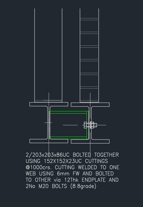
A typical detail is to connect these twin beams with UC offcuts, welded to one beam and bolted to the other.

If these are spacaed at say 1m cc. does that reduce the effective length to 1m?

or will they assit with load share

or both?

I have had a user friendly document in the past covering this but i cant find it again.

discssion will be appreciated

 
Replies continue below

Recommended for you

Edit- after reading other posts it looks like you cant simply rely on these beams being restrained just becasue they are connected.

but is there a way of calculating the benefit?

Note- i work on domestic projects with beams spanning less than 4 to 5m with occasional longer beams in there.

Still interested in discussions
 
More pictures would be nice

A typical detail is to connect these twin beams with UC offcuts, welded to one beam and bolted to the other.

If these are spacaed at say 1m cc. does that reduce the effective length to 1m?

That sounds a reasonable well restrained diaphragm connection given it has a rigid connection at one end. The effective length will be reduced significantly but will likely be more than 1m. Buckling analysis will give better answers.
 
Thanks human909.

image attached of twin beam.

I agree that it will be retrained (and that also doent take into account anthing else coming into the beams - joists or any precast units)

I thought guidance might have been covered in text to avoid a bbuckling analysis.


 https://files.engineering.com/getfile.aspx?folder=4d58dd73-49d6-430a-91d0-fd8a34ed4e5f&file=twin_beam.png
There have been quite alot of LTB questions recently from what I've seen. You are far from the only one looking for such guidance.

LTB is complex, effective length is just a short cut that will cover 95% of the LTB cases engineers face. Torsional restraints don't fit neatly into the effective length framework so codes just hand-wave them away to 'rational buckling analysis'. Codifying them is likely complex because their behavior depends significantly on the stiffness of the connections and the members.

We've had hundreds of posts on this topic, with numerous references linked. I have yet to see one simple set of guidance. Though if anybody can contribute then I'm all ears too.

twin_beam_1_gghfga.png


P.S. I'll try to run a buckling analysis on this one.... Give me a bit.
 
The udnerstanding of LTB isnt an issue. Its how this theory is applied in the real world (with examples such as the above)

I would be interested in the following results.

Length changes. say 4m, 6m . 8m.

loading. say a lodd of euqual 10 kN/m on each beam and an unblanced loading of say 10 kn/m on one and 20 kn/m on the other.

It might also be more useful to use a more slender UB than a UC shown.

All ears!!

 
Doing all that would be quite extensive! I'll keep it simple.
 
ha . understood adn is appreciated!

out of interest what are you using?

 
I use use Nastran. It is FEA so it is more adept at complicated shapes and connections. But it is also more sensitive to getting your model conditions right. Agent666 uses Mastan2 which is more straight forward and relatable to theoretical buckling behaviour but is less flexible in dealing with real world connections.

This series is a decent read by Agent666. It uses the Australia/NZ code but should be similarly applicable to your local code.

I won't be completing an analysis today, but I'll try to follow through in the near future. Doing this properly is non-trivial.
 
Luke2020 said:
I have had a user friendly document in the past covering this but i cant find it again.

If you do find it, I would love to know of it so that I might check it out.

Luke2020 said:
I thought guidance might have been covered in text to avoid a buckling analysis.

For me, a practical solution would be this:

1) Assume no load sharing between beams and, instead, design both beams for the worst case load originating from either side. There will be some load sharing but determining the amount will be complex and dependent, in part, on torsional behavior. Take any load sharing as a nice bonus that you can keep in your back pocket to help limit any differential deflection that you might get between beams/wythes without the interconnection.

2) Check lateral torsional buckling on each individual beam assuming the unbraced length to be the distance between UC off cuts, just as you suggested.

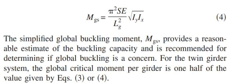
3) Check global system buckling using the equation shown below which can be found in the thread referenced by phamENG.

Keep in mind that, to the extent that any of the following are true, the tendency towards global system buckling will be reduced:

5) If vertical shear capability between your wythes would prevent the wall from rotating to match the rotation of the beam pair.

6) If the supported wall itself would tend to resist lateral motion of the beam pair.

7) If the interconnection between beams would produce composite section behavior for lateral bending. The equation below assumes no such composite behavior. At the proportions of your system, I would actually expect the UC cut offs to in fact produce a meaningful amount of composite behavior. And, to that end, a stockier UC off cut will tend to improve composite behavior.

c01_agoawi.jpg
 
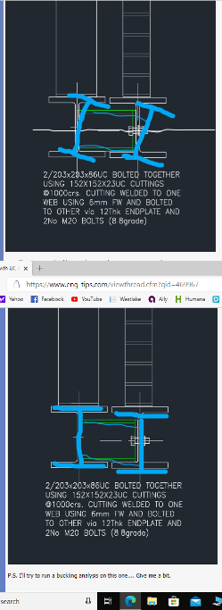
The twin beams are inter connected, but not considered well/adequately braced. The single bolt near the neutral axis can't prevent the beam to rotate, provided the beams are loaded differently, one tends to drag the other due to combined settling/torsional effect. Since fastening can be difficult, I would consider adding top and bottom cover plates to make it boxed beam.
 
retired13 said:
The single bolt near the neutral axis can't prevent the beam to rotate,

I believe that it can with an end plate as detailed by OP, at least within the range of the level of restraint required for the bracing function. In fact, I believe that this is the primary point of having the interconnection between beams.
 
I think the detail might need some modification to achieve it, as the plate tends to move with the web it attached to. I hope these two types of movement wouldn't occur, stiffeners may help to an extent.

t_aywbuj.png
 
retired13 said:
...as the plate tends to move with the web it attached to.

I agree but that only tells us that this is an imperfectly rigid joint. And, of course, all rigid joints are imperfectly rigid. The question here is whether or not this particular joint would be rigid enough to successfully brace the beam. And I argue that it would be. We should keep in mind that it actually takes very little force to brace things in most situations.
 
Just feel too many items are relying on the stiffness/stability of this connection. Damages may not be the connection itself, but the linked/supported elements. Be careful.
 
I agree with what most of what kootk said. Those are pretty rigid joining elements with pretty rigid connections. For the sake of LTB I'd consider them rigid.

Here are my steps running this with FEA buckling analysis.

Stage 1.
1. Pick a single beam and a working length. 200UB25 6m long
2. Create 3D FEA model and check against the theoretical reference buckling moment. (As determined by calculation and checked via LTBeam software)
3. Confirmed that the FEA linear buckling results within 5% of theoretical value.

Stage 2.
1. Create twin beam setup with 2 150UCs
2. Run various scenarios and compare the buckling moments.

Conclusions:
-The stub connection significantly increases the buckling moment. The back calculated effective length is significantly less than the spacing between the stubs.
-The stubs provide significant torsional restraint as well as lateral rotational restraint. The reduction in lateral rotational restraint results in an shorter effective length.

So to answer the original question. Yes it is safe and conservative to use effective length equal to the beam spacing. I would be confident in this assumption for a broad range of similar connections. It also quickly becomes apparent that that with these connections and those beams so closely spaced that twin beam buckling can be the dominant buckling mode. As far as load sharing goes that is a can of worms I'd prefer to leave alone.


Incidentally. I followed up with playing around with joists (but no deck) as lateral bracing as was discussed a little off topic in this thread:

A quick check shows that even a relatively flexible joist with a relatively flexible connection it still significantly reduces the effective length. EG with a 3m spacing of a relatively flexible connection we still get effective lengths of about 4m. You really don't need much stiffness to stop buckling.

Below is an image of the buckling with a REALLY flexible joist. Unsurprisingly there is little increase in the moment capacity, But with members of more realistic stiffness you quickly see improvements in buckling capacity.
200UB25_cfbbab.png
 
The single bolt connection is liking a pivot point. Really stable?
 
retired13 said:
The single bolt connection is liking a pivot point. Really stable?
Yes. And I appreciate your doubt, if you have seen my comments in other threads you would know that this is the sort of question that I've sometimes queried.

At least two things going on here.
1. The two bolt connection (not a single bolt) is pretty stiff for what is needed. Its a long way from a moment connection but it is also a long way from a pivot.
2. Even if it WAS a pivot then it still offers significant restraint against buckling as it also offers stiffness against vertical and horizontal movement of the attachment point.

I'll try to get another picture.
 
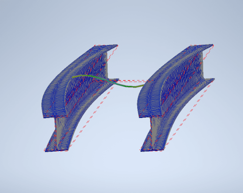
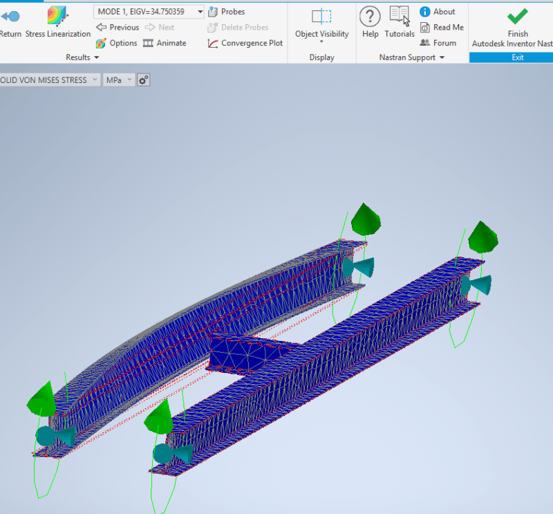
Here is the behaviour of the model with welded one side and NO connection the other side. Both beams loaded with constant moment and pinned end. The theoretical buckling moment is 33.3kNm at effective length of 6m. The obtained one here is 34.75kNm. Close enough to theory.

unnconnected_aakz2i.png


I'll follow up with a hinged connection. (a perfect hinge is non trivial but I should be able to do it)
 
Status
Not open for further replies.

Part and Inventory Search

Sponsor