Hi, long time no post...!
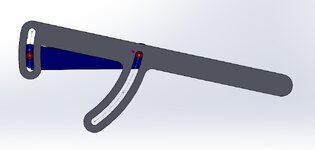
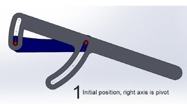
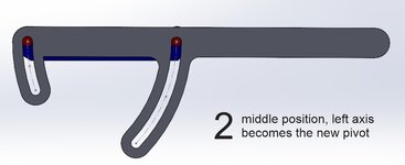
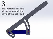
I cannot make this work, I have two parallel pieces, the blue one is fixed and the handle uses two pivot points, once one of the extremes of the small path reaches the end, it becomes the pivot for the rest of the movement of the large path.
What I did:
- added a point at the center of each red axis
- drawn the paths and also added a point in the mid of each paths
- made two path mates, one for each axis, where the axis center point is the vertex and the path... well the path
If I leave this as it is, the part revolves in any non parallel position that satisfies both mate paths, not good
Then I tried a symmetry mate using the point in the center of the axis and the point in the center of the path for the small path, making it min distance zero and max distance path length/2, this constrained the movement of the small path perfectly
then I wish to do the same for the large path I get into trouble, cannot do it.
if I try to mate the planes parallel, also can't do it
How would you do this so the blue is fixed and the grey one moves parallel to it and its limited to both paths and depending on its place at the ends of the small path or the top of the large path one of the axes becomes the pivot point?
Thanks


