Continue to Site

Eng-Tips is the largest engineering community on the Internet

Intelligent Work Forums for Engineering Professionals

  • Congratulations SDETERS on being selected by the Eng-Tips community for having the most helpful posts in the forums last week. Way to Go!

Two process refrigeration systems working together controls?

Status
Not open for further replies.

AlbertaCA

Industrial
Nov 15, 2016
7
Hello,

We are planning to install a second refrigeration plant. It will work with the other one, sharing the same vapor, liquid and hot gas lines.
It is a propane refrigerant system. Has anyone worked or is working on a similar system? What are some of the things to note? I can not find much info
through process books. Thank you.
 
Replies continue below

Recommended for you

Having refrigeration trains in parallel is very common in the industry. Certainly the system can be designed (or upgraded) to manage operation of two trains in parallel. You have failed to mention any specific details, so the reply cannot be more specific.

Revamp designs always bring some amount of uncertainty because of potential bottlenecks within the existing system. Have these been thoroughly evaluated? Some things on top of my head:
- load sharing between the refrigerant compressors?
- sufficient surge vessel volume to ensure initial fill for two trains?
- size and layout of compressor suction and discharge lines (any significant delta P difference between two trains)
- utilities balance: enough utility streams for both trains?
- footprint/layout
- PLC/DCS (existing control system upgraded, or a separate/new one in parallel)
- F&G and SIS/ESD system hierarchy
- existing piperacks able to handle the load of new piping
- etc.

There is plenty of subjects to be addressed. Hopefully you and your team will manage to identify all important issues.

Dejan IVANOVIC
Process Engineer, MSChE
 
Thank you, those are good points. We have most of them worked out, or planed on paper (studied).
The part I'm trying to work through is the controls. One system is three centrifugal compressors the other system will be two screw 1600 hp.
They'll be two hundred meters apart, with the chilling trains between. The new system will have all the vessels and condensers of its own.
So far as control, on suction pressure or one base load and the other swing. Caution or question, is receiver levels balance?

 
It is very hard to comment without a sketch/PFD. Is the feed gas split between two trains on flow control? How the outlet temperature from refrigeration plant is controlled at present, and have you performed any dynamic analysis for the future configuration(s)?

You need to take extra caution with regards to operating points of the compressors, i.e. to avoid operating any of them at very low efficiency part of their curve. This will largely depend on what size of the compressor you intend to purchase, as well as the type of control you configure. Base/Peak may be or may not be a good option. The same applies for equal load sharing.


Dejan IVANOVIC
Process Engineer, MSChE
 
You can expect lube oil degradation on the new screws if they are operated on fixed speed - this is going to end up in the chiller kettles and coat the tubes...

Receiver levels may balance out if you have a balance line between the one for the old machines and that for this screw set ?

Post us a sketch of the overall shared scheme and process controls if you want more feedback.
 
Hi,
I am not familiar with refrigeration system but one word of caution is:
Be careful that centrifugal compressors don't operate in parallel with PD compressors. There are bunch of problems if they do.
Shayar
 
Hello,

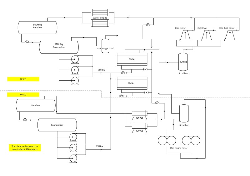
I've tried to attach drawing, hope it works.
Pipe sizes;
24" suction
6" C3-liquid
4" hot-gas


C3_dgdnst.jpg
 
Presume the economiser on the new screw machines is working with flash gas routed / shared with the existing interstage scrubber.
Normally, there is a hot gas bypass around the condensor to maintain a constant pressure on the receiver - this should be there for both trains - but, in this case, if you have this as a common overhead pressure equalising line between the 2 receivers, that will make things easier to control. In that case, a level balancing line between the 2 receivers would be all this required to keep receiver levels equal. For this to work, the new air cooler propane exit temp should be the same as that for the existing water cooled unit. You havent stated what the pressure is fore the new receiver ??


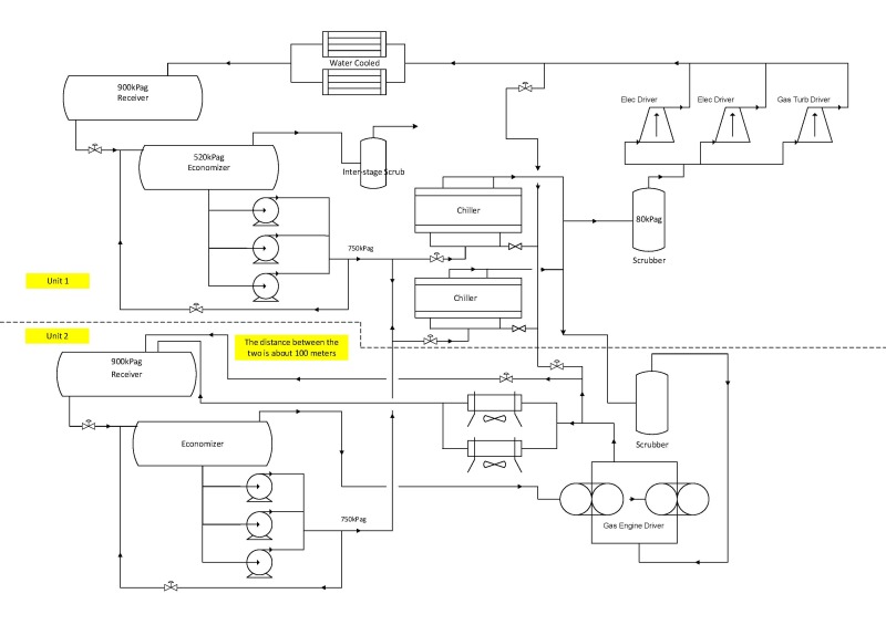
Yes to your first statement. I was still drawing it up. There will be no balancing line between the two receivers, nor a over head line.
C3_doqpef.jpg
 
You've now added the hot gas bypass around the condensor on the new train, but there isnt one on the existing train? - thats a pity since you'd save some compression power by subcooling with water since you wouldnt need to generate as much subcooling through the economiser.

Agreed, you could run one train's compressor on normal suction presure control, while the other operates on fixed flow cascaded by low set suction pressure control. Can see some complications on how you would split the duties between the existing and new pump sets. No details given on the process side duty at the 2 chillers.
 
There is no hot gas BP around the CW condenser, or will be. On thing I have found out is our new receiver pressure will be 1300-1400 kPag (winter-summer).
For simplicity I only put down two chillers. The duty in the existing system is 4500KW @-15, which does fluctuate in the summer and winter. The new addition it will
change to 10000KW @-25.
 
If your new receiver pressure is 1300-1400kpag, then it is critical to get the same temp on subcooled propane to the pumps on both existing and new trains, else you'll have vapor breakout where the 2 streams mix before getting into the chillers.

As you said, from what you've disclosed so far, there is still an operational risk of unequal levels in the 2 receivers - this may have some effect on how the pumps share out the propane feed to the 2 chillers for the case when one receiver level has dropped low - this would occur due to the low set LC override at the receiver on to pump flow controls. Essentially, when one receiver level has dropped low, you could have the entire 10MW cooling load appearing on the other receiver / pump set.
 
Status
Not open for further replies.

Part and Inventory Search

Sponsor