Remember my recent "help me find an ancient transistor" thread;
thread240-443861
I'd like to understand these boards a little more, please walk with me as I describe the scene.
Here's a reminder of what they look like:
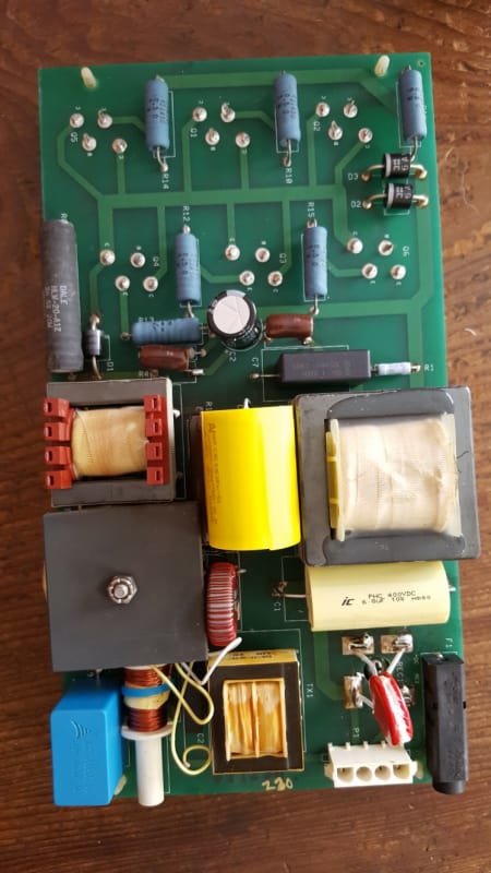
I referbed five of these things and laying on my stomach installed them into their 19" rack-mount boxes stuffed under heated cauldrons of 409-like detergent and DI water. Bolted to the bottom of these 2ft x 2-1/2ft x 2ftdeep tanks are the four ultrasonic transducers under a heavy SSteel cover.
Each of these 19 inch racks had 230V 80mm metal computer-style fans. One was failed in one of the racks probably leading to the worst vaporized caps seen on some of the boards.
One I'd refurbed they'd installed and had re-failed, in the last week before I got there yesterday. I was surprised to find they were 230V not the expected 120V and it's 10A fuse had blown, a bad sign. :/
I pulled out the board and checked the base-emitter diode drop across one of the 6 paralleled transistors and it was measured as 0.01V in either direction and both the B-E and B-C junctions. I decided it was a shorted transistor which will light up a fuse in a big hurry. I unplugged the transistors and yep, correct. One had turned into a three terminal 0.1Ω resistor.
I installed the four boards I'd brought and everyone of them fired up and made the cleaning table sound like it had 30 million angry bees in it.
Interestingly they have 4 red LEDs on the rack front panels that tell you each channel is driving its transducer.
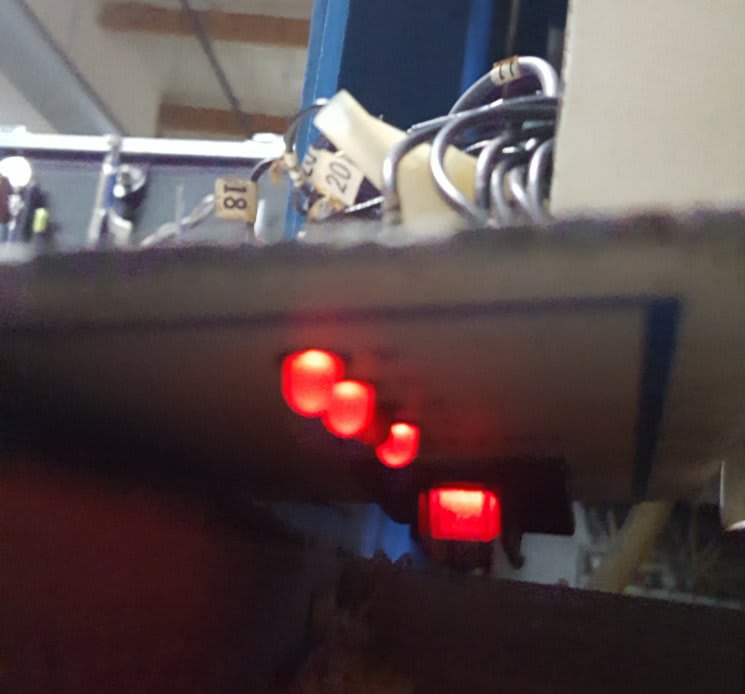
They used those LED driving current coils and ran a lead to each transducer thru each coil. I liked its simplicity and galvanic isolation. I left them all run for an hour while I troubleshot a problematic VFD that was, luckily, 10 feet away instead 400 feet as usual.
Once they all seemed to stay running I disconnected the one without a working fan until they get the replacement fan installed.
While I was there I decided to scope out what was going out to the transducers. It was hard. Not knowing what to expect I swapped to my TEK high voltage probes (1000V) that I got optional with the scope a bazillion years ago. I had to hook the ground to a wire I stuffed in the back of the Molex plug and then I had to hold the probe tip against the neighboring pin on the back of the board without touching or slipping while doing a no-handed push-up and poke the freeze button on my scope. 'Don't talk to me and go away guys!'
Here's what I saw..
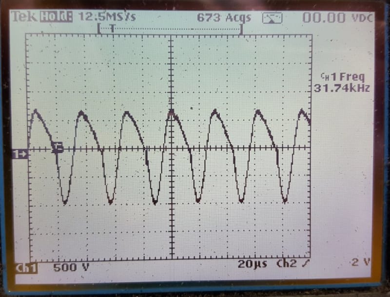
~32kHz driving the transducers at 1,700 Volts pk-pk! I then noticed my scope probe would draw an arc as it got close to the pin. Sheesh.
If I reduced the sweep I got fish..
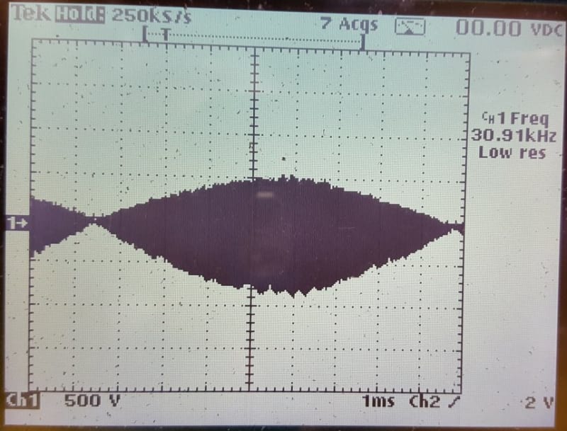
Further sweep reduction - schools of fish:
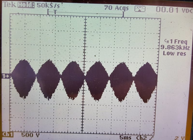
These patterns looked the same on my boards as it did in these pictures of a yet-to-fail untouched factory board.
Anybody know what's going on here? Why the envelopes? Deliberate or incidental?
I hope the 1,700V isn't across the 1,500V transistors.. But with a fist full of transformers on the board (see above) I'm hoping not.
And on a different bent do you have any reasons I can't make a 32kHz oscillator, (555? or divided crystal), amplify it with a BIG MOSFET and drive the 1.00Ω transducers thru an impedance matching transformer, avoiding all the chokes and limited lifetime caps and swarms of transistors? The schools of fish make me balk/wonder.
Keith Cress
kcress -
thread240-443861
I'd like to understand these boards a little more, please walk with me as I describe the scene.
Here's a reminder of what they look like:
I referbed five of these things and laying on my stomach installed them into their 19" rack-mount boxes stuffed under heated cauldrons of 409-like detergent and DI water. Bolted to the bottom of these 2ft x 2-1/2ft x 2ftdeep tanks are the four ultrasonic transducers under a heavy SSteel cover.
Each of these 19 inch racks had 230V 80mm metal computer-style fans. One was failed in one of the racks probably leading to the worst vaporized caps seen on some of the boards.
One I'd refurbed they'd installed and had re-failed, in the last week before I got there yesterday. I was surprised to find they were 230V not the expected 120V and it's 10A fuse had blown, a bad sign. :/
I pulled out the board and checked the base-emitter diode drop across one of the 6 paralleled transistors and it was measured as 0.01V in either direction and both the B-E and B-C junctions. I decided it was a shorted transistor which will light up a fuse in a big hurry. I unplugged the transistors and yep, correct. One had turned into a three terminal 0.1Ω resistor.
I installed the four boards I'd brought and everyone of them fired up and made the cleaning table sound like it had 30 million angry bees in it.
Interestingly they have 4 red LEDs on the rack front panels that tell you each channel is driving its transducer.
They used those LED driving current coils and ran a lead to each transducer thru each coil. I liked its simplicity and galvanic isolation. I left them all run for an hour while I troubleshot a problematic VFD that was, luckily, 10 feet away instead 400 feet as usual.
Once they all seemed to stay running I disconnected the one without a working fan until they get the replacement fan installed.
While I was there I decided to scope out what was going out to the transducers. It was hard. Not knowing what to expect I swapped to my TEK high voltage probes (1000V) that I got optional with the scope a bazillion years ago. I had to hook the ground to a wire I stuffed in the back of the Molex plug and then I had to hold the probe tip against the neighboring pin on the back of the board without touching or slipping while doing a no-handed push-up and poke the freeze button on my scope. 'Don't talk to me and go away guys!'
Here's what I saw..
~32kHz driving the transducers at 1,700 Volts pk-pk! I then noticed my scope probe would draw an arc as it got close to the pin. Sheesh.
If I reduced the sweep I got fish..
Further sweep reduction - schools of fish:
These patterns looked the same on my boards as it did in these pictures of a yet-to-fail untouched factory board.
Anybody know what's going on here? Why the envelopes? Deliberate or incidental?
I hope the 1,700V isn't across the 1,500V transistors.. But with a fist full of transformers on the board (see above) I'm hoping not.
And on a different bent do you have any reasons I can't make a 32kHz oscillator, (555? or divided crystal), amplify it with a BIG MOSFET and drive the 1.00Ω transducers thru an impedance matching transformer, avoiding all the chokes and limited lifetime caps and swarms of transistors? The schools of fish make me balk/wonder.
Keith Cress
kcress -
![[lol]](/data/assets/smilies/lol.gif "[lol] [lol]")