Continue to Site

Eng-Tips is the largest engineering community on the Internet

Intelligent Work Forums for Engineering Professionals

  • Congratulations IDS on being selected by the Eng-Tips community for having the most helpful posts in the forums last week. Way to Go!

Unable to get dimensions for individual plies separately 1

Status
Not open for further replies.

LaeeqRana

Mechanical
Apr 24, 2016
28
thread327-286047
Hi, I am using CATIA V5 for composite modeling on curved surface. I am using grid method for modeling, in manufacturing module I am unable to get dimensions for individual plies separately.In reality Plies in one laminate must have different dimensions due to curvature. (Inner most ply must have smallest dimension). Kindly help me out in this regard. Secondly how can I manipulate Title block in Composite Ply book ?
Thanks
 
Replies continue below

Recommended for you

What do you mean by get dimensions? Create you onw title block for composites. I use standard Ply book macro, then I delete all in the background and run our company title block.
Upload you 3D. I'll take a kook.
 
Dear Janial thank u for your concern. Regarding Dimensions, let's suppose, I apply a laminate of 5 layers on curved surface ( half tail of symmetrical aerofoil) using Grid method in CATIA V5. After flattening of plies, In Drafting all flattened plies have the same dimension. But, In reality each ply should have different dimension because they are applied on curved surface, not on a flat surface.Inner most ply should have smallest dimension and outermost should have largest dimension, but this is not the case. Is it built in feature of CATIA or am I missing something ? Sorry I am unable to upload 3D, will upload soon.
I tried to use your suggested method to create my own Title Block, but once I created ply book using Composite Ply Book, I was unable to delete Standard composite Title Block. But, it was possible to create, delete or customize Existing Title Blocks in an empty worksheet, by using commands Set Background----->Insert----->Frame and Title Block.
Would you please help me out in this regard.
Thanks
 
Personally I don't think than you'll see a big difference between flat patterns. Even if it's on a curved surface so what? It's only 5 plies therefore the difference will be minimal. Any way you don't have to care about flat patterns because you will manufacture a part with at least of 0.5" excess material. Wouldn't you? 3D needed for a deep review.
 
Dear Jenial, you are absolutely right. This would not make much difference as there will be minimal difference in lengths, and you will also have excess material for trimming purpose. But you don't always have to use such small no. of plies. let's assume you have to apply a core of honeycomb between these plies, or you have spars and ribs or any other complex situation. Then there should be remarkable difference between first and last ply dimensions, but this is not the scenario in my case. I am attaching a file with more than 70 plies on a curved surface, kindly guide me how can I get the exact dimensions of each ply. Am I missing something in Design process ?
 
 http://files.engineering.com/getfile.aspx?folder=00229024-e976-40fc-b9c5-1a76d68b6df4&file=Composite.zip
With such slightly formed surface you won't see any difference between first and last ply. Maybe if you will use CFM as propagation type you will see a little difference. CFM propagation available within CFM license.
Untitled_ozeh0l.jpg

Believe me if you will model a part with core you'll see a difference between first and last ply. To get better flat patterns you may use 2 master surfaces. One below core and one over core. Personally i don't do that because on all of my parts i have at least 0.5" excess. If you have a specific part (real part) with issues don't hesitate to contact me. I'll try to help.

Cheers,

Jenia Ladkov
 
Dear Jenia Ladkov, Thank you so much and sorry for being late. I tried CFM as well but it gives the same result. My point is that let's suppose on half airfoil I apply three layers of composite, then core of honeycomb and there is no core at ribs and spars places and then last layer. Last layer should follow ups and down bcz honeycomb is missing in some areas and last layer must have different dimension as compare to first one. This does not happen in my case and I get same dimension for all layers. I am attaching a file. Kindly help me out in this regard and let me know where I am doing something wrong.
Thank you again.
 
 http://files.engineering.com/getfile.aspx?folder=372d0773-7591-4927-b197-929ffaf08e28&file=Query.rar
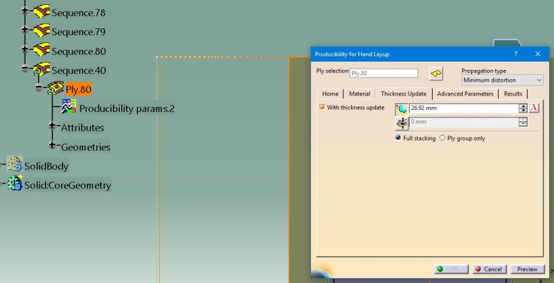
Create a core and move it after seq 40. Run producibility analysis with following parameters
Untitled_tjitty.jpg

As you can see first ply is wider than last. Also try to avoid using the same name for the plies.
This is also working without core. Just check with thickness update option.

p.s This thread shall be moved to catia section on this board so other catia users may learn something.
 
Dear Jenia Ladkov, Thank you so much for your assistance. I am using crack version CATIA V5-6 R2014. I could not find thickness update option in producibility of this version. I tried but could not get different dimensions for first and last plies. Is it because of "Crack version" or "R2014" or am I missing something else? Which version are you using ? Is advance Producibility feature you are using introduced by INCEPTRA? I am attaching another file, would you please share the files with flattened plies of this and previous one.
Thanks.
 
 http://files.engineering.com/getfile.aspx?folder=69fc1db6-b24d-48ed-b346-bc3f318cdb3c&file=Composite_part.rar
Dear, It did work. Thank you so much for your help. Is it possible to generate composite PLY Book for an assembly file? And would you please tell me the script to get plies weight in title automatically. Same script works for non composite parts but does not compute plies weight.
Thanks
 
No it's not possible. Ply book works only with staking objects. As for the script you can workaround on Ply book macro. You can also use attribute link to get ply weight.
Why do you need ply weight to be shown on drawing?
 
Ok Thank you. I was asking because VB code has attribute link to get part mass but still it does not show ply mass in drawing. If you use other VB code provided by CATIA to generate TITLE BLOCK, it shows PLY mass in Drawing. Same link doe not work in PLY BOOK. Is there any reason ? Secondly using seed at different locations creates flattened Plies of different size and boundary. What should be location of seed point to get accurate flattened PLY in case of HAND LAY UP ?
Thank you.
 
I guess ply book macro works together with some CAA application. I have contacted Dassault if they can give some info regarding VB and composites. Awaiting for an answer.
Yes you are right different seed point location will give you different flat pattern. It's hard to say where is the right location for a seed point. It depends on shape and other factors.
Start with geometrical center location and run producibility analysis. If it's not looking good then switch to indication, move seed point and see how this affects analysis.
 
Thank you for your concern and effort. Does the flattened ply using different seed points has same area(seed point does not make any difference in final dimensions for cutting ) ? Is there no standard for seed point? Is not seed point at geometrical center is impractical in case of hand layup ( because its the starting point for the placement of plies on mold surface ). What should be the propagation type for glass fiber, carbon fiber and kevlar ? Is it necessary to define material properties like warn steering in producibility ?
Thank you so much for your time and support.
 
Definitely different area because of different shape. Again it's hard to say where seed point should be. It's not a matter of material it's a matter of a shape. To better understand how to pick seed point you have to get yourself to a shop floor and see what's going on in a real time.

It's always better to define as much properties as possible. Have never checked if this will affect flattening.
If you don't want to get to much rings [indian] from a shop floor guys it's better to define warn steering.
If you have seed point issues with a specific part just upload a 3D here and i'll try to help.

p.s Do you use laser projector for plies lay-up?

Cheers,
Jenia Ladkov
 
Ok. Thank you for your support. Would you please let me know the attribute link to get material of non-composite parts in Drafting Title Block ? Is it possible to get material name of all assigned composite materials in drafting? I will upload parts, I would not be able to get reasonable flattened plies.
No , I don't use Laser Projector for Hand Lay up.
Thanks again.
 
Here's how to use attribute link. Before using this make sure you have material or whatever property in a CATPart.

There are several ways to export composite data from Catia.

First one numerical analysis

Second one: You can export plies table from Catia to Excel and then you can insert it into a drawing.
Third one: You can use core sample. Personally i prefer core sample because of its associativity.
Use Core sample drawing view style to bring lay-up table into a drawing. Let me know if you need help on that.

Cheers,
Jenia Ladkov
 
Thank you so much. Also in my opinion, core sample is better option [smile]. I will let you know if I find difficulty in Plies Flattening.
Thanks.
 
In Catia V5 R27 will be an opportunity to bring fully associated with stacking table into a drawing. You said you use hand lay-up. Prepregs or wet lay-up?
 
Status
Not open for further replies.

Part and Inventory Search

Sponsor