Continue to Site

Eng-Tips is the largest engineering community on the Internet

Intelligent Work Forums for Engineering Professionals

  • Congratulations IDS on being selected by the Eng-Tips community for having the most helpful posts in the forums last week. Way to Go!

Unbraced Length of Compression Chords in 3D truss 1

Status
Not open for further replies.

Stickengnerd

Structural
Feb 12, 2020
5
In working through the design of a (3) dimensional truss with an inverted triangular cross section and a span of nearly 100ft, what would the unbraced length of the (2) top chord compression members be? Is it accurate to consider the unbraced member length the distance between the diagonals, in both the Lz and Ly directions? Or do you have to consider the unbraced member length the entire length of the truss? Or perhaps the answer is somewhere in between, using the distance between the diagonals with a multiplication factor? Note: The roof deck will not help in this situation, as it is a remodel intended to remove columns below, and the roof deck is to be suspended below the truss.

Does anyone have any recommendations of good texts or papers to read on (3) dimensional truss design / box truss design that might address this, or anything else I'm not thinking of?


 
Replies continue below

Recommended for you

PhamENG - The link works if you slice off the [] and img from the ends.


StickengNerd -

In this case, I suspect that the diagonals are sufficient to braced the top chord in each direction. Though this is a case where (if I assumed that lower unbraced length) I'd use the Direct Analysis method and some lateral notional loads to see if the P-Delta analysis caused any problems.
 
JoshPlumSE-

I applied a horizontal line load along the top of one chord. It had almost no effect on the deflected shape, or stability of the overall structure. P-delta doesn't appear to be a problem so long as the columns are horizontally braced. I suspect that I can use the lower unbraced length of the distance between the diagonals, but as of yet, I haven't found anything to justify that assumption, other than basic engineering sense and experience.

Thanks for your input.
 
Thanks, Josh - must have picked up/left off something when I copied it.

Have you considered using the relative column bracing requirements in Appendix 6 of AISC 360? The commentary's example is essentially a less complex 2D version of what you have.
 
Celt83-

Thanks for that. Some useful info there, even though it's about box girders, not box trusses. I would assume they would act similarly.
 
Stickengnerd said:
I suspect that I can use the lower unbraced length of the distance between the diagonals, but as of yet, I haven't found anything to justify that assumption, other than basic engineering sense and experience.

You can absolutely do that in my opinion, and do it based on engineering sense as you say. Sometimes I fear that we've gone so far down the automation path that we no longer have the ovaries required to trust our own, sound instincts. Long before concentric trussing failed to adequately brace your chords across a panel, you would experience:

1) Axial strength failure of the webs or;

2) Unacceptably high shear deformations in the truss (effectively a sway column condition).

The problem is sort of self solving in that respect.
 
I think if both legs of the chord angle are sufficiently connected (welded), you can take the distance between the joints as unbraced length. Here is a Euro paper for laced column that may help (see page 60-17). Link
 
This is one of the good reasons for the Direct Analysis Method. The concept of "buckling length" of a member can be tricky to predict with accuracy.... at least for unusual cases.

The idea behind the Direct Analysis Method is that, if you follow the requirements of the method, your analysis will find the buckling. This is imperfect, especially where torsional buckling is concerned. But, adding the notional loads (or member imperfections), P-Delta analysis, and the TauB stiffness reductions lead to an analysis with a more reasonable design result than you'd get by merely using a good KL value in your code check.
 
There's also little point in attempting to check any kind of global, lateral torsional buckling. The thing's a gargantuan tube which is, after all, the entire point of this structural form.
 
Thanks for the help. You guys provided some good references.

KootK- I agree with you. Axial strength of the webs and deformation of the truss controls much more than global buckling does. As for trusting sound instincts, while I agree wholeheartedly with you on that comment, that doesn't stand up to a lawsuit if there's a failure. In this world's sue happy culture, every tiny thing has to be justified.

Retired13 - Thanks for the link.

PhamEng - According to App6, it appears as if I have to take a slight reduction because the bracing is at an angle instead of perpendicular, but even with that reduction, the buckling doesn't control the design.

Thanks all.
 
Stickengnerd said:
As for trusting sound instincts, while I agree wholeheartedly with you on that comment, that doesn't stand up to a lawsuit if there's a failure.

I disagree. Not everything that one needs to execute structural engineering can be found in a code book or an accepted reference. The best defense against liability exposure is to simply know your craft well. I used the term instincts so as to avoid being condescending. That appears to have been a mistake. Let's try this:

KootK said:
Sometimes I fear that we've gone so far down the automation path that we no longer have the ovaries required to trust our own, sound instincts fundamental understanding of structural behavior.
 
For what it's worth, I believe that you can find definitions of unbraced chord length in both the Canadian steel standard and the Steel Joist Institute standard.
 
Ovaries? Perhaps something gender neutral like cajone...er....how about "guts" :)


Meh... I'm not sure that cajones actually is gender neutral. And guts doesn't really have the shock value that I was gunning for. Given the very, very long history of courage being defined in terms of the testicle, I've decided to make a point of defining my own courage in terms of my ovaries until I feel that adequate redress has been achieved.

c01_zhulmm.jpg
 
It's not gender neutral - it was a joke...and a poor one at that.

 
What is this sarcasm that you speak of?? We don't have that on planet KootK.
 
Yeah I too see it as mostly straight forward. Appropriate detailing the connections to the box section is a mild challenge and may noticeably affect the capacity of the member.
 
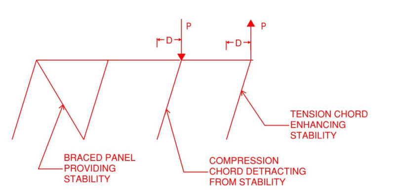
@JoshPlumSE: I'd like to discuss the two statements below. The first is from this thread; second is from an older thread: Link. We disagree on something quite fundamental here so it should be interesting to hash out.

JoshPlumSE said:
I'd use the Direct Analysis method and some lateral notional loads to see if the P-Delta analysis caused any problems.

JoshPlumSE said:
For a truss, you still have P-Big Delta and P-Little Delta. The panel joint deflections are the "big delta" effect and the chord curvature between panel points would be the "little delta" effect. It's analagous to a braced frame turned on it's side.

I submit that there is no such thing as P-Big Detla on a transversely loaded truss. The reason for that is that there is no net-compression on the cross section taken as a whole. The sketch shown below shows what I feel would truly be an analogous, braced frame situation. And it has no P-Big Delta. Or, more precisely, it has P-Big Delta demands that cancel out as I submit that they do with a truss. I could have put the loads on the frame itself rather than on the two lean too columns but I often find this presentation more salient.

c01_o1ncvv.jpg
 
Status
Not open for further replies.

Part and Inventory Search

Sponsor