eli28
Aerospace
- Oct 20, 2019
- 109
Hello everybody,
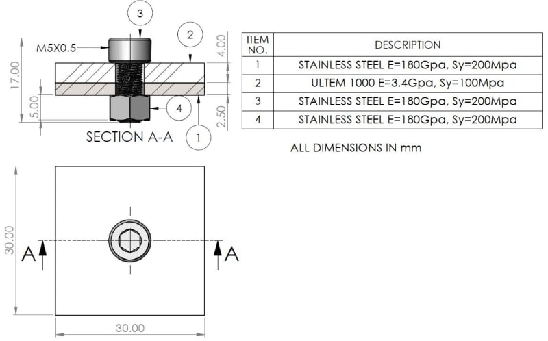
I have a bolted joint that is not common - one of the clamped members is made of ULTEM 1000.
Here is an illustration on the simplified clamped joint I tried to analyze:

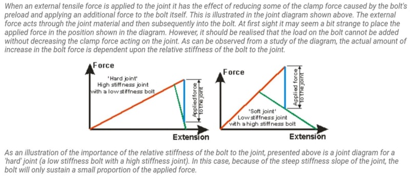
In most cases we tend to use a joint in which its stiffness (Km) is larger by far than the bolt's stiffness (Kb).
It leads to the situation that in service bolt "feels" mainly the initial clamping force (Preload), Fi, and a small portion of the external load. This portion is determined by the relative stiffness Coefficient C=Kb/(Kb+Km) by the relation P_bolt=C*P, While P is the external exerted load and P_bolt is the relative part the bolt carries. In the typical cases of clamping steel members, it equals to C~0.8, and hence the entire force the bolt "feels" in service is Fi+C*P.
In my case the mutual stiffness of the clamped members is rather low thanks to the the ULTEM 1000 plate.
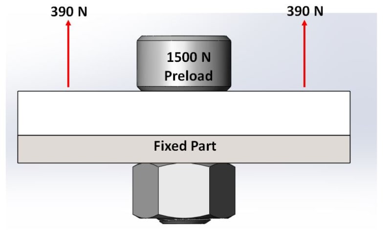
The preload in my case is 1500N and the external load P=780N.
I calculated and found that C~0.9, what means that the bolt is the main carrier of the external force, P, and that the clamped members should not "feel" a meaningful change in the initial clamping force, Fi, through Service.
I found that the bolt axial tensile force Fb=2200N and the clamped plates compression force Fm=-1430N.
I also checked in the literature that it makes sense and here you can see the right graph in which it shows the case like mine in which there is a "soft joint":

I was quite sure I am OK and predict fine what might be, but when I used the simulation to approve my prediction I was surprised to see that the opposite happened and that the members are the ones to take most of the external load like in the traditional case of clamping stiff steel plates.
What can you say about it?! Can someone verify in his own simulation tool what might happen?
Here is how I described the simplified problem in the simulation:
*pay attention that the upper (ULTEM 1000) member has a uniformly distributed force – a total of 780N.

I have a bolted joint that is not common - one of the clamped members is made of ULTEM 1000.
Here is an illustration on the simplified clamped joint I tried to analyze:

In most cases we tend to use a joint in which its stiffness (Km) is larger by far than the bolt's stiffness (Kb).
It leads to the situation that in service bolt "feels" mainly the initial clamping force (Preload), Fi, and a small portion of the external load. This portion is determined by the relative stiffness Coefficient C=Kb/(Kb+Km) by the relation P_bolt=C*P, While P is the external exerted load and P_bolt is the relative part the bolt carries. In the typical cases of clamping steel members, it equals to C~0.8, and hence the entire force the bolt "feels" in service is Fi+C*P.
In my case the mutual stiffness of the clamped members is rather low thanks to the the ULTEM 1000 plate.
The preload in my case is 1500N and the external load P=780N.
I calculated and found that C~0.9, what means that the bolt is the main carrier of the external force, P, and that the clamped members should not "feel" a meaningful change in the initial clamping force, Fi, through Service.
I found that the bolt axial tensile force Fb=2200N and the clamped plates compression force Fm=-1430N.
I also checked in the literature that it makes sense and here you can see the right graph in which it shows the case like mine in which there is a "soft joint":

I was quite sure I am OK and predict fine what might be, but when I used the simulation to approve my prediction I was surprised to see that the opposite happened and that the members are the ones to take most of the external load like in the traditional case of clamping stiff steel plates.
What can you say about it?! Can someone verify in his own simulation tool what might happen?
Here is how I described the simplified problem in the simulation:
*pay attention that the upper (ULTEM 1000) member has a uniformly distributed force – a total of 780N.


![[bigsmile] [bigsmile] [bigsmile]](/data/assets/smilies/bigsmile.gif)