ACivilLife
Structural
- Nov 18, 2024
- 7
Hello everyone,
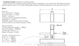
I have some questions about a wall footing design example from the ACI design handbook (see image).
1. In general, how would you get the axial force effects from a wind load on the wall footing. My thinking is let's say you had 12-inch CMU exterior walls that are 20 ft tall on two sides of a building with a 60 ft x 60 ft footprint. To keep things simple, let's say you had a uniform 20 psf wind load blowing on one of the 60 ft faces (in the plane of the walls). Could you calculate the axial force effects on the wall as follows:
Total Load on a single wall per ft of wall height = 20 psf (30 ft) = 600 lbs/ft
Total Moment at base of wall = wL^2/2 (assuming fixed-free) = (600 lbs/ft)*(20 ft)^2/2 =120,000 lbs-ft
Moment of Inertia of Wall = 1/12*bh^3 = 1/12 * (1ft)*(60ft)^3 = 18,000 ft^4
Maximum Bending Stress at Base of Wall = Mc/I = (120,000 lbs-ft)*(30ft)/(18,000 ft^4) = 200 lbs/ft^2
Maximum Axial Effect on Wall per ft length of wall = (200 lbs/ft^2)/(1 ft) = 200 lbs/ft (Wall thickness = 1 ft nominally)
Is my line of thinking correct for getting the axial load effect?
2. Several allowable soil-bearing pressures are provided in the ACI Design Example. Where do these come from? I know you can get basic load bearing values from IBC Table 1806.2 or the geotech report, but would the different allowable soil pressures for the lateral combinations be some combination of lateral bearing and sliding resistance from Table 1806.2? Also, why would there be a different allowable soil-bearing pressure for D vs. D+L?

