Eng-Tips is the largest engineering community on the Internet

Intelligent Work Forums for Engineering Professionals

  • Congratulations waross on being selected by the Tek-Tips community for having the most helpful posts in the forums last week. Way to Go!

Uneven heating on HVAC heating coil (air-water HEX, copper fin tube) 2

Status
Not open for further replies.

Neo47

Mechanical
Aug 3, 2021
3
0
0
US
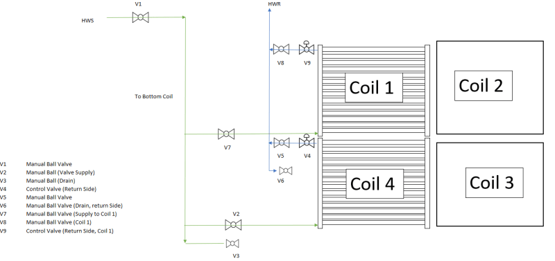
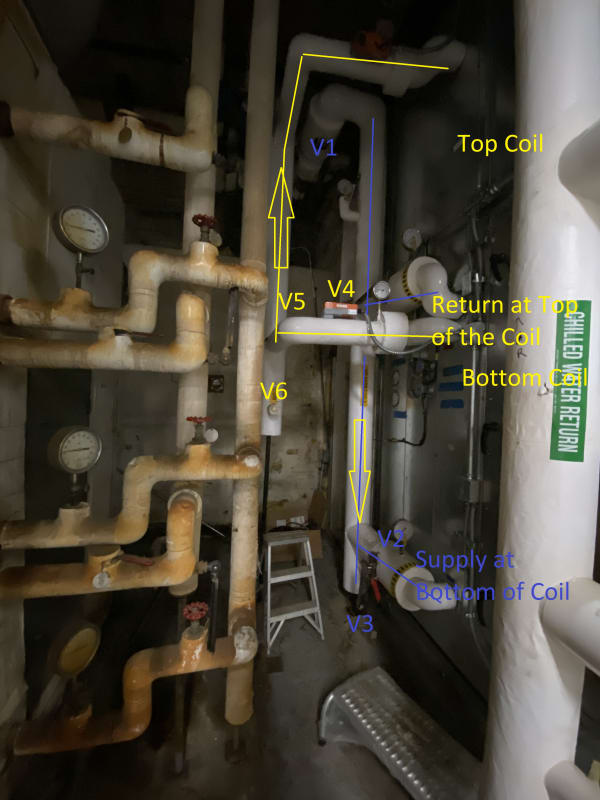
We have a air-hot water heat exchanger on an Air handling unit that has uneven heating. Attached photos explain the situation.

IMG_1440_b1enzf.jpg


IR_7757_exg8nh.jpg


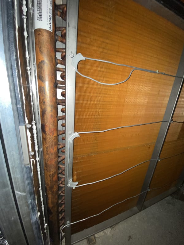
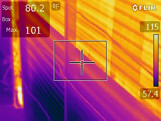
The coils are made of copper. The air handlers use 100% outside air. The IR photos show that when the valve opens hot water fills up the supply header but does not flow into the tubes at the bottom half of the coil. During our investigation, we opened the control valve at 10% increments and noticed that until the valve open % is greater than 35%, there is no flow into the tubes at the bottom half of the coil. The IR camera picture was taken when valve was open 25%.

During cold outside air conditions, the reduced flow through bottom part of the coil leads to freeze stat trips and AHU shutdown. We have cleaned and blowdown the water side of the coil multiple times to remove any debris, but the uneven water flow still remains.

The coil manufacturers have not been helpful so far in solving the issue. Has anyone seen a similar problem in heating coils and if so share what the source of the problem was and the solution adopted?

Thanks
 
Replies continue below

Recommended for you

I guess that the combination of pressure drop across the control valve, pressure drop through the individual coil circuits and coil supply and return header design is sub-optimal.
 
Hi Neo,

A few questions:

Has there been a water audit done to see what the actual flow rate and pressure drop through the coil is compared to the original design?

Do you have photos of how the coil is piped? Supply connection location/return connection location?

How was the coil flushed? Can you describe the process.

Lastly,was a chemical pipe cleaner run through this system at some point? Asking because I ran into a situation once where, the client ran pipe cleaner through the system and all the gunk/debris ended up getting trapped in the coils.

 
Does the hot water supply enter the coil from the bottom or the top? It looks like it's entering from the top, based on the image, and I think that will give you problems getting the air vented out of it.
 
Your problem is likely caused by airlock in the lower tubes. There are air bubbles in these tubes that require a certain minimum differential pressure to get them to move out of the tubes. Why this is happening and preventing it requires a detailed examination of the piping to and from the unit. Fully opening the control valve every hour or so for 30 seconds could be one quick and dirty solution, which could be accomplished with a timing relay.
 
Can you post a picture of the piping schematic for the coil? But I do agree with posts above, it looks like you have air in the coil. The air must be bled out or the coil will not transfer heat correctly/evenly.
 
Coil connection should be such that water enters from the bottom in a counter-flow pattern to air flow(ie cold air coming in first makes contact with cold water exiting the coil).The counter-flow connection will ensure a steady a LMTD across the whole depth of the coil and maximise heat transfer. If the connection is done this way air entrapment in the coil is a possible cause as well as inadequate water flow. It is also worth checking the water tube velocity at the measured flow rates to see if it is operating in the laminar flow range. If the flow is laminar heat transfer will be very low.
 
Last time I saw an IR photo of a coil showing cold area at the bottom was because it was full of mud/debris inside, and by gravity they stick to the bottom.
Easy to remedy.
 
So the header runs the entire height of the coil, correct? But water is only going in the top half of the tubes?

It would possibly make sense if the "supply" header was at the top half and the "return" header was at the bottom half. Under low-flow conditions, all of the heat could be removed before the water makes its way down to the lower half. But, that does not see to be the way the coil is piped. Looks like the header runs the entire height of the coil, so you would expect all rows to be receiving flow. So I am now agreeing with others about possible air bound.

Would still like to see how it is piped.
 
You may need to have the header tube removed to see what is happening to the coils. I'm betting they are plugged. Contamination will settle to the bottom, particularly if the supply is from the bottom as the lowest coils are the first place that water will flow, carrying the contamination with it.

Back-flushing may be a way to push blockages back out, but the flow rate needs to be high enough that the pressure drop through the unblocked tubes is high enough to push blockages out. The seems likely to be a difficult task to perform as installed.

Not sure how big an air bubble would be required to block flow - is it large enough to do a pressure release test? Block off the exit and pump the pressure up to some reasonable level with water and then see how much water is ejected when the inlet pressure is let off? Either that or pull a hard vacuum on the coil and the allow water to enter so there is no air.
 
Thank you all for the responses. I will try to address all the questions here. The piping for the coils is shown below.
@immsk
Has there been a water audit done to see what the actual flow rate and pressure drop through the coil is compared to the original design?
I am not aware of such a study performed for the coil.

Do you have photos of how the coil is piped? Supply connection location/return connection location?
Yes, Please see below
Piping_Layout_cl2gjd.png


IMG_3557_jnebav.jpg

Please note that the IR picture initially posted is for the coil number 4 at the bottom of the arrangement. The same issue is seen on coil 3.

How was the coil flushed? Can you describe the process.
Basically they drained the water-glycol mixture from the coils and refilled it. From talking to the plant mechanics, I understand that a back flush was not performed.

Lastly,was a chemical pipe cleaner run through this system at some point? Asking because I ran into a situation once where, the client ran pipe cleaner through the system and all the gunk/debris ended up getting trapped in the coils.
Not to the knowledge of the plant mechanics

A lot of you have suggested air trapped in the coils. If there is air in the coil, shouldn't it be at the top of the coil instead of being isolated at the bottom half of the coil?

@3DDave and BenMacier
This is a unit that was install 4 years ago, so I assume the presence of debris or contaminants at the bottom tubes of the coils should be low. Still, since this is an issue at the lower tubes of the lower coils, I think doing a proper back flush of the coil could be an effective next step in solving the problem.
 
If the problem goes away when the control valves are fully open, the problem is air that does not flush out until a certain differential pressure across the coil is reached. There are bends and elevation changes within the coil. They may not be exactly equal in different sections
 
Using two control valves to control the same temperature may be part of the issue. If one is set slightly different from the other, one may shut completely as the other valve modulates. Consider running both valves in parallel from the same controller.
 
If I understand this right your issue is not at full flow when it's all at the same temp, but only when you try and regulate / reduce the water flow?

What type of valve is V4? If its a butterfly then you won't get much flow under 30% open.

As said earlier, unless all your coil valves are on the same opening percent, you might be starving the lower coils of flow.

Do those coils have side by side vertical headers for flow and return? It's not easy to see on your first picture what the piping arrangement is between the coils and the headers.

Are you able to measure actual flow vs what the coil is designed for?


Remember - More details = better answers
Also: If you get a response it's polite to respond to it.
 
There should be a strainer on the HWS piping upstream of the coils. There should be a manual air vent valve at the top of each coil and automatic air vents at the high point of the HWS and the HWR piping above the coils. There should have been plugged tees at each coil offset HWS and HWR piping to allow blowout of each coil. Confirm pressure drop across each coil is the same to confirm equal HWS flow across each. Confirm airflow is uniform across the coil face and not concentrated at the bottom. If the fluid is not glycol solution consider putting freeze protection pump across bottom coil to operate when outdoor temperature is less than 33 degrees F.
 
Status
Not open for further replies.
Back
Top