Continue to Site

Eng-Tips is the largest engineering community on the Internet

Intelligent Work Forums for Engineering Professionals

  • Congratulations KootK on being selected by the Eng-Tips community for having the most helpful posts in the forums last week. Way to Go!

Uneven suspended load/counterbalance 1

Status
Not open for further replies.

rsm7400

Industrial
Mar 6, 2012
52
I'm sure this question is easy but I do not remember my statics calculations right now haha. I have a beam that is 79" long and weighs 130lbs. I have a part that weighs 190lbs that will be uniformly suspended by 2 straps 44" apart. The first strap needs to be hooked on the bar started at 4". I can move the pick up spot to practically anywhere along the length of the bar. Where do I need to pick up so that the load is balanced?
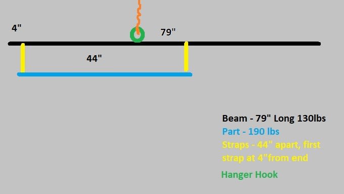
Suspended_Load_t2vmxl.jpg


Thanks in advance!

________________________________
Ryan M
Quality Engineer
3d Printer Hobbyist
 
Replies continue below

Recommended for you

so CG of bar is midspan, CG of "part" is at 4+44/2 = 26,
balance point is at (130*79/2+190*26)/(130+190)

"Hoffen wir mal, dass alles gut geht !"
General Paulus, Nov 1942, outside Stalingrad after the launch of Operation Uranus.
 
Hi rsm7400

Split the 190lb into two forces of 95lb and place them as point loads at the straps 44” apart. Place the 130lb as a point load at the centre of the 79” beam. Take moments about the beam from the left hand end:-

95*4” + 95*48” + 130*39.5” = x * (95+95+130)

X = 95*4” + 95*48” + 130*39.5”
—————————————————————————
(95+95+130)

That should give you the lifting point position X.

From an academic point of view that’s how to solve the problem, however if this is a real life situation I would be concerned about lifting from a single point

“Do not worry about your problems with mathematics, I assure you mine are far greater.” Albert Einstein
 
Thank you so much! I havent touched statics in 15 years, the last place I worked we could pick up every part/fixture by hand.

________________________________
Ryan M
Quality Engineer
3d Printer Hobbyist
 
Hi rsm7400

You’re welcome

“Do not worry about your problems with mathematics, I assure you mine are far greater.” Albert Einstein
 
You may have simplified your description to make your question simple and clear.[ ] However what you have shown is an unstable mechanism.[ ] If (when) your spreader-beam begins to tilt, even infinitesimally, the geometry of the total lifted load (spreader-beam plus straps plus "part") changes because the straps will always be vertical.[ ] The system's centre of gravity moves slightly to the left, so the spreader-bar tilts a bit more to compensate.[ ] Away she goes!

At the very least, you MUST ensure the rectangle in your diagram CANNOT turn into a parallelogram.[ ] Adding a pair of crossed diagonal ties might do the job, but only if they have adequate axial stiffnesses.
 
Yes thank you :) I was aware of that but good to restate it. We just moved the part with the gantry moving very slow. All was stable and flat and loaded up very nicely!

________________________________
Ryan M
Quality Engineer
3d Printer Hobbyist
 
Status
Not open for further replies.

Part and Inventory Search

Sponsor