Eng-Tips is the largest engineering community on the Internet

Intelligent Work Forums for Engineering Professionals

Uniform Force Method — Bracing Connections to Column Base Plates 1

Status
Not open for further replies.

ANE91

Structural
Mar 31, 2023
10
0
1
US
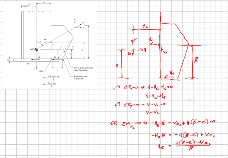
I am having trouble deriving the equilibrium equations provided in Fig. 4-22 of AISC's Design Guide 29, entitled "Vertical Bracing Connections - Analysis and Design." Refer to Sections 4.2.4 and 4.3 for a discussion of the analysis procedure(s).

Considering Example 5.12, I can only replicate the solution using the equilibrium equations of Fig. 4-22. I cannot reproduce this solution using traditional UFM equations. My Mathcad sheet is attached.

I have scoured the internet for this derivation and cannot find it. Thornton's AISC lecture on YouTube glosses over this case. The Seismic Design Manual goes into some detail on page 257 of 439. I understand that it is founded in moment equilibrium, but I cannot sketch or visualize the configuration that produces the two equations in Fig. 4-22.

Can someone demonstrate this derivation, please?
 
 https://files.engineering.com/getfile.aspx?folder=e9657a8c-dd6f-4f64-88ea-06217902c9b6&file=UFM_SpecialCaseIII_Algebra.xmcd
Replies continue below

Recommended for you

Can you post a picture of your mathcad analysis?

I do not believe special case 3 applies to the gusset-to-base plate case, which has connections to both the horizontal and vertical interface. I think you'd need to use the general UFM case where "e" would be the beam eccentricity "eb" but with a negative value.

The two equations in figure 4-22 are derived by taking moments about the control points "Hc" and "Hb", which allows you to solve for these two forces without calculating "alpha" and "r".
 
Yeah, case 3 is not appropriate here. By following case 3 you have Hb equal to zero, Hc equal to 72.6k, and are dumping significant moment into the column. This does not match the assumptions in example 5.12.

I'd try starting over with the general UFM case, with the workpoint set at the intersection of column and brace centerline, "eb" will be a negative dimension down to the top of the base plate.
 
Thank you for the suggestion. Negative e.b gets me closer to the "correct" H.b (negative) and H.c (positive). However, it also introduces wonky V results and a moment into the "beam" (baseplate). It also does not help me to understand the derivation of the Fig. 4-22 equations.

My reading of UFM suggests that the equations don't change much between the various use cases, only the parameters really change. It is all based on geometry. For example, setting gamma to zero in the non-orthogonal case simplifies to the general UFM equations.

I am fundamentally missing something in the geometry of the base-plate case wherein the general UFM equations do not match up. It is simple algebra, but I need help getting there.
 
Screenshot_2024-08-12_134057_kgohqd.jpg
 
Status
Not open for further replies.
Back
Top