Continue to Site

Eng-Tips is the largest engineering community on the Internet

Intelligent Work Forums for Engineering Professionals

  • Congratulations KootK on being selected by the Eng-Tips community for having the most helpful posts in the forums last week. Way to Go!

Uniform Thickness Comment 3

Status
Not open for further replies.

eli28

Aerospace
Oct 20, 2019
109
Hello,

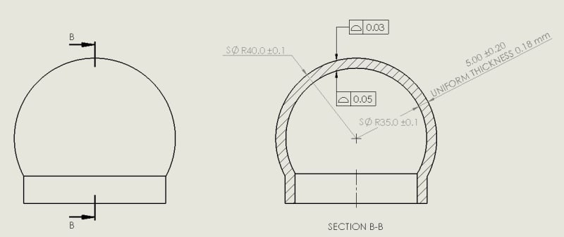
I saw for the first time an engineering department in which the drawings contain a remark "Uniform Thickness XXX".
Here is an example for making it clear:
Original_dn2cu1.jpg


I never saw a similar comment and I would like to know if it complies with the ISO Standard (or even any other standard).
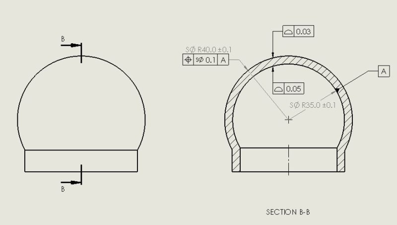
I thought that maybe an alternative form is using the profile control of both surfaces and the eccentricity of the inner/outer spheric surfaces.
I think that the UNIFORM THICKNESS = Outer_Surface_Profile + Inner_Surface_Profile + Centers eccentricity limitation
Here is an example of an alternative form of writing the same, at least in my opinion:
Alternative_Uniform_thickness_vuni2n.jpg
 
Replies continue below

Recommended for you

Standards do not forbid writing notes to specify controls that are not covered by them.

I use the ASME standard, but I noticed that the radii of your spherical surfaces are directly toleranced and you specify profile for them. It is questionable per ASME and most will say invalid so if there is not some fundamental difference with ISO, it is also invalid for ISO. Anyway, If it is on purpose, the profile only controls form. The tolerances on the radii are much larger than the profile tolerances and they will influence the thickness uniformity variation between different parts.
 
Hey, I lately asked the same question regarding the profile given for a toleranced radius, and I was told that (at least) in ISO it is possible.
The meaning is indeed controlling the form or more intuitively controlling the waviness around the average radius.
In fact, it's quite like flatness controls a planar surface.

I still think that a uniform thickness is controlled by the profiles control since it limits the waviness around the average value, and hence limits the distribution around it...Distribution level means uniformity, not ? don't you think so [neutral]?
 
If the purpose of the thickness uniformity limitation is only to control the variation of thickness per part, then I agree.

If thickness variation between different parts is important too - the tolerances on the radii will have a big influence.
 
Indeed, that's the aim - controlling variation within the same part.
Thanks
 
Regarding whether your calculation is correct or not - that is up to someone with ISO knowledge to confirm or correct it.

Per ASME I think it would be correct (although the size and sphericity requirements would need to be specified differently) because what the ASME position controls is the actual mating envelope - an ideally spherical envelope that touches the highest points on the surface. The same type of envelope would be used to simulate the datum. Each control intended to evaluate the form limits the variation between two spherical boundaries and effectively it would take care of the gaps the actual feature has from the envelope that contacts its highest points. The displacement of the center point of the considered feature from the datum point is another factor as you are aware. This seems to confirm your calculation per ASME, but I don't know regarding ISO.
 
Thank you very much for answering.
I hope someone with ISO knowledge will be able to confirm the practical side I presented in the attached drawing views.
 
@eli28
the first drawing is double dimensioned.

the second drawing what is the mounting dia, the i.d. or o.d. that should be the datum -A-
I would have preferred S radius dimension on the out side
eliminated the inside Sperical and retained the wall thickness.
how are they inspecting the inside radii?
 
This is just an example (a simplification of a real problem) so I didn't really pay attention to the inspection capability's consideration.
Another question please - Is the fact that I add a tight profile control on the surface makes the actual tolerance field be tighter than this reflected by the radius range dimension?
 
eli28 said:
Another question please - Is the fact that I add a tight profile control on the surface makes the actual tolerance field be tighter than this reflected by the radius range dimension?

If it is indeed legal per ISO to specify profile in conjunction with directly toleranced sphere radii as you were told, then as I mentioned the profile tolerances will only control the form and will not affect the tolerance range of the radii of the spheres between different parts. It will only affect the uniformity of each radius within a single part. For example, the 40+/-0.1 radius can be either 39.90-39.93 everywhere or 40.07-40.10 everywhere (or of course something in between), so the entire +/- range is intact. A comparison example is cylindricity tolerance. The cylindricity tolerance can be tight and can be used on a feature with a large tolerance for size (diameter). The tight cylindricity tolerance will not affect the range of diameters between different parts but the measured diameters within a single part will not differ from each other more than what the cylindricity tolerance allows -roughly speaking the local diameters will not vary by more than twice the cylindricity tolerance.

There may be some nuances with this though because keep in mind that checking the range of local diameters is not how cylindricity is evaluated so what I described is probably just a rough estimation of the effect of form tolerance on the range of local diameters/radii.
 
agree, except for this and depending on the product

Quote "will not differ from each other more than what the cylindricity tolerance allows" unquote
the parts can be from the high limit or low limit, the cylindricity is independent attribute.

if I am incorrect please provide the link to ASME
 
mfgenggear, consider for example a cylinder of diameter 20+/-0.2. Without a cylindricity requirement, it can be produced tapered with the small end diameter 19.8 and the large end diameter 20.2. If cylindricity is specified, for example within 0.05 - that part will not pass. Parts tapered between 19.8-19.9, 19.9-20.1 19.9-20, 20.1-20.2, or similar variations within the size range may pass. That's basically what I was saying. Do you disagree?
 
Burunduk
Yes agree,
The cylindricity tolerance has to be held
Roundness, taper,and straightness, but the diameter tolerance is independent.

There are examples for bearing journals
Require .0005 diameter tolerance but require
.0001 inch cylindricity.
 
mfgenggear,
The requirements are independent, but I believe it is safe to say that a bearing journal that passed the .0001 inch cylindricity inspection can not possibly have a diameter that ranges more than between X and X+.0002 inch. Do you think otherwise?
 
yes I do because I have manufacture hundreds of parts with those requirements.
 
I also heard others saying what Burunduk said.
The form tolerance may limit the variation of the size that should have an average value inside a wider tolerance field.
Let me know if we are wrong.
A reference to a standard will be great.
 
mfgenggear,
You are probably thinking of the drawing requirement of size tolerance.
I am talking about the actual variation of local cross-section diameters within a single part that passed the cylindricity inspection. The cylindricity tolerance zone is two coaxial cylindrical boundaries with a radial distance of the tolerance value. The local radii of one actual produced feature cannot vary more than the cylindricity tolerance zone size. Therefore the local diameters can't vary more than twice that value. They can be anywhere within the specified size range but the variation within one feature on one part cannot exceed twice cylindricity tolerance.
 
Burunduk
In the old days we used an instrument, and there is bunch still a round. Called a sheffield.
Combination optical with steel carbide tips
Calibrated by gage blocks prior to use.
This is what used myself to verify .0001 inch tolerance.
I think we are talking apples and oranges.
Yes the tolerance of the diameter has to be with in the diameter specified.
Part diameter can vary from part to part.
With in blue print tolerance.
How ever a single part must be the same size across the diameter in order to maintain .0001 inch cylindricity.
I sold hundreds of parts accepted by customers who accepted them and are flying in the skies.
 
mfgenggear said:
Part diameter can vary from part to part.
With in blue print tolerance.
How ever a single part must be the same size across the diameter in order to maintain .0001 inch cylindricity.

That is what I was saying:
"The tight cylindricity tolerance will not affect the range of diameters between different parts but the measured diameters within a single part will not differ from each other more than what the cylindricity tolerance allows"

I believe the bolded portions say the same thing (I suppose that by "same size" you don't mean precisely the same size but as much uniformity as it takes in order not to be rejected by cylindricity inspection).

 
Status
Not open for further replies.

Part and Inventory Search

Sponsor