Eng-Tips is the largest engineering community on the Internet

Intelligent Work Forums for Engineering Professionals

Unknown 115 kV component 4

Status
Not open for further replies.

Burt M

Electrical
Jan 24, 2024
4
0
0
US
Unknown_component_115_kV_ti2mu2.jpg

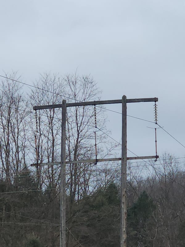
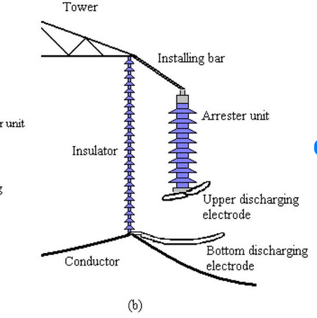
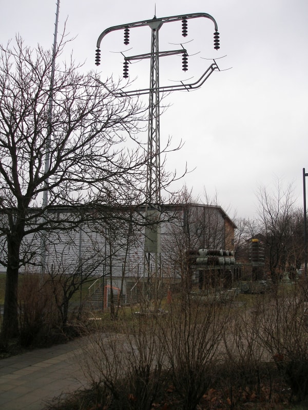
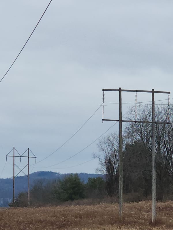
Does anyone know what the curved devices are underneith the conductor insulators?
 
Replies continue below

Recommended for you

Probably intended to catch, and short, a conductor if the insulator string fails. Might not do much in high winds, though, when the forces on the insulator string are also the highest.

When one this sentence into the German to translate wanted, would one the fact exploit, that the word order and the punctuation already with the German conventions agree.

-- Douglas Hofstadter, Jan 1982
 
I don't think they are intended to catch the conductor, but to short it to ground so the relays can see it as a fault and trip. The trees in the area should be a clue as to the purpose.
 
That's two votes for an arrester with a gap. I do not see anything resembling an arrester in the photo, though. Before MOVs and SIO2, the industry used rod gaps, which I considered. Seems a lot simpler to put the rod gap in parallel with the insulator, though. I like David's suggestion best.
 
I've never seen an OHL design that has a "conductor catch" before.... but I could be wrong! Best practice would be to select the proper hardware to lower the probability of mechanical failure in a high consequence area.

It appears that there's no shield wire above the line so my vote is still for lightning protection.
 
I believe the horns are electrodes designed to direct an arc away from the insulator and thereby lengthen and extinguish the arc. The arc starts at the smallest gap then moves up the horn due to the plasma being very hot. Just like a Jacob's Ladder.
 
I agree, it appears to be installed either for lightening protection or arc suppression.
I would expect the devices to be grounded for either of these two functions.
I see what looks like a bushing on the lower end of the supports, but I don't see a ground on any.
The one on the right appears to be grounded, but I think that is another line crossing in front of the bushing because I don't see grounds on the other arrestors. I dont think they were made to support any load (fallen conductor) because the lower crossarm is smaller than the conductor crossarm.
 
Hi Folks,
Here's another photo of the 115 kV devices.
No grounds are shown to each of the devices.
Not sure how they would work as lightening protection or arc suppression without grounds.
Burt
Unknown_115_kV_component_Photo_2_eqwrnf.jpg
 
The photos are not close enough to show the lack of hardware bonding to a pole ground. The path would be along the crossarm and down the pole. A ground would be needed for David's suggestion as well.

There once was a product called a safety yoke that was intended to catch and short circuit falling distribution conductors. Never caught on.
 
Have to agree with David here. In the first picture, is that a distribution line perpendicular and under the transmission line?
I would want something to short out before transmission lines fell on distribution lines.
 
The second picture is taken from about 40’ away. Could be the distribution is just above the camera view…
Theres also a distribution line in the picture running parallel with the transmission.
 
As as been said its a surge arrestor and would take a lightning strike down to ground.
I'm not the best at math but if the cable fell away from the bottom of the insulator it would not fall even close to the curved unit.
My thoughts are the curved conductors are likely attached to a metal bar and the earth conductor is out of shot.

 
From how the photo was taken, it doesn't seem much like gapless arrester to me (it appears too thin, and I don't see an insulating coating or bushuing, but I could be wrong). That design reminds me of some features of early 20th-century power lines, for which a "conductor restraint system" was provided to prevent them from falling in case of insulator string breakage. At the same time, those metallic elements served as arching horns: directing the arc downward rather than parallel to the insulator string reduced the risk of breakage due to thermal shock. I am attaching a photo of a fairly similar situation in Germany (from Wikipedia).
BTU_Cottbus_100_kV_Tragmast_qftkti.jpg


Si duri puer ingeni videtur,
preconem facias vel architectum.
 
Unlike the other images I found of gapped surge arrestors, the unknown device does not have sheds. Are the sheds on newer gapped devices unneeded and simply exist so that the arrestor can be used in multiple configurations?

It seems like the airgap is much too small for the device to be a grounded conductor catcher. At least I assume the primary purpose of a conductor catcher was to ensure a solid fault path to ground.
 
Another couple of images: a drawing of the original 110 kV line in Germany and a similar example (but from a few years later, at 60 kV) in Sardinia. Can you tell if the material composing the rods in the OP's photo is insulating? Could it be some sort of "insulating conductor catcher"?
60_kV_line_Sardinia_1924_fbo0q2.jpg
testa_palo_110_kV_lauchhammer_ug3xz4.jpg


Si duri puer ingeni videtur,
preconem facias vel architectum.
 
Status
Not open for further replies.
Back
Top