Continue to Site

Eng-Tips is the largest engineering community on the Internet

Intelligent Work Forums for Engineering Professionals

  • Congratulations KootK on being selected by the Eng-Tips community for having the most helpful posts in the forums last week. Way to Go!

Unrestarined Cold Form Design for Monoslope Roof

Arun4567777

Structural
Aug 11, 2020
87
"Hello everyone,

I'm reviewing a design featuring purlins supporting a standing seam roof. Since the purlins are unrestrained the top as well as bottom flange, I need to design for both gravity and wind uplift loads. To prevent lateral-torsional buckling (LTB), I want to implement a bridging system to restrain both the top and bottom flanges.


The roof has a monoslope configuration with a slope of 5 degrees.

Would a rigid fixed strut system with diagonals at the ends be an effective solution?

What about Sag rods top to purlin bottom with diagnols at end on ridge.
 
Replies continue below

Recommended for you

The standing seam roof doesn't provide top flange restraint?
 
Can you provide a sketch of the size and the proposed materials used?

The standing seam roof doesn't provide top flange restraint?
I don't count on standing seam roofs to provide any diaphragm action. They are typically supported with clips that can slide in the seams.
 
The AISI requires Base test method to be done to arrive at R value for Stsnding Seam.
Plus the client wants it to be designed as unrestrained.
 
We are using Z Purlins with 200mm Depth spanning 7.5m
 
Your client is pretty knowledgeable if they know what that means. Are they aware that it will result in increased sizing?

I don't necessarily count on the standing seam for diaphragm action, but for compression flange bracing I feel it's more than adequate. Especially for light-gauge purlins. I know that's how the PEMB suppliers get them to work out. That plus some dodgy moment splices.
 
Since we cannot take any advantage of the Standing Seam. Can anyone suggest some discrete bracing arrangement that we can give for the purlins.
 
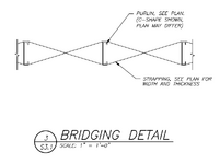
Typically, the standing seam roof is designed to float. You really shouldn't count on it for bracing or for diaphragm action (unless it's a through fastened system or has testing done per S908). A couple of good documents are AISI D111 (https://scholarsmine.mst.edu/ccfss-aisi-spec/235/) and the attached pdf. For bracing the purlins, I have seen this type of bridging used:
1731676885443.png
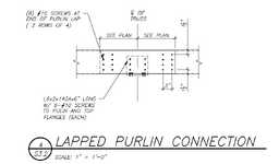
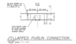
I would use a "lapped purlin" design so you can count on 2x the section modulus over the support.

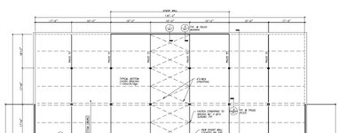
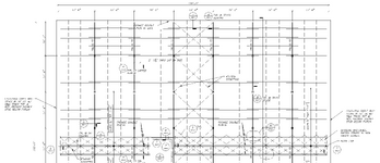
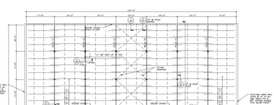
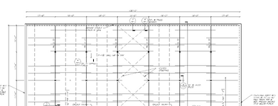
For diaphragm bracing you could also use a discrete/truss system. Here is a snippet from a truss project:

Bottom Chord Plan:

1731677019044.png

Top Chord / Roof Plan:

1731677239340.png

1731677163579.png
 

Attachments

  • 41920711-Purlin-structure-design.pdf
    244.8 KB · Views: 3
  • 1731677067156.png
    1731677067156.png
    102.4 KB · Views: 1
  • 1731677088163.png
    1731677088163.png
    170.6 KB · Views: 1
  • 1731677151725.png
    1731677151725.png
    128.9 KB · Views: 2
You still need to provide bracing for overall stability (wind and seismic) in addition to the local bracing of the purlins. Perhaps, the purlin bracing will do both but it is something to check.
 
PEMB manufacturers do usually add purlin bracing when using standing seam roofs to help with flexural capacity of the members.

You can find erection details for Nucor (one of the large PEMB manufacturers) online. While sizes aren't listed, it can be a good starting point look at how the system works.

 
You still need to provide bracing for overall stability (wind and seismic) in addition to the local bracing of the purlins. Perhaps, the purlin bracing will do both but it is something to check.
Agreed.
And to clarify the X-bracing down the center in those drawings was your diaphragm truss if I remember correctly.
 
Thabks for your responses.

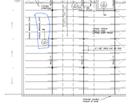
"Could you please clarify the location of Section 3 S3.1 in the drawings?
I believe the dotted line extending from the ridge to the eave indicates the strapping arrangement shoen in thst section, which ultimately connects to a truss at the ridge. Please confirm.
 
PEMB manufacturers do usually add purlin bracing when using standing seam roofs to help with flexural capacity of the members.

You can find erection details for Nucor (one of the large PEMB manufacturers) online. While sizes aren't listed, it can be a good starting point look at how the system works.

The documents cannot be accessed.
 
For this application, channel struts are probably the best bracing option. Look through the photos on the link below for an example:

 
Thabks for your responses.

"Could you please clarify the location of Section 3 S3.1 in the drawings?
I believe the dotted line extending from the ridge to the eave indicates the strapping arrangement shoen in thst section, which ultimately connects to a truss at the ridge. Please confirm.
1731961861136.png
 

Part and Inventory Search

Sponsor