Continue to Site

Eng-Tips is the largest engineering community on the Internet

Intelligent Work Forums for Engineering Professionals

  • Congratulations cowski on being selected by the Eng-Tips community for having the most helpful posts in the forums last week. Way to Go!

Unrestrained Basement Wall 1

Status
Not open for further replies.

pioneer09

Structural
Nov 7, 2012
67
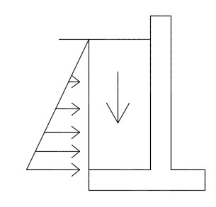
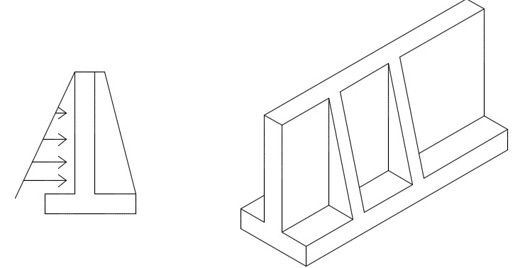
Looking to see if anyone has some tips/ideas to design the unrestrained basement wall as seen in the attachment. My initial design was a retaining wall. Like a typical project in the design-build field, the contractor thinks this is nuts and way overdesigned. Per the usual, they did not have this amount of concrete figured in their contract and are super concerned about cost. After talking to their concrete subcontractor (due to lack of belief in the engineers design), the subcontractor believes (2) pilasters extending 4' into the soil as denoted in red will be sufficient to brace this wall. I took this approach and looked at the wall spanning as a continuous beam and used the pilasters as supports. The force at these pilasters becomes very large and to prevent overturning and sliding the 4' length will not work. I assumed this would be the case and the length required becomes extreme and I will hear major push back from the contractor.

I have thought of other possible scenarios that may work:

1. Span wall the 36' between cross walls (unrealistic due to reinforcing and depth needed)
2. Place steel beams on the outside of the wall and somehow tie to the basement wall (beam would span horizontally to cross walls.)

I know my design is not dictated by the contractor that had overlooked this when bidding, however I want to give the most efficient and cost effective solution possible. I am at somewhat of a lost on this. Any ideas would be greatly appreciated.

Thanks
 
 http://files.engineering.com/getfile.aspx?folder=a9982551-37e0-44e5-a7fb-48cc570f2b66&file=2017-05-15_Unrestrained_Basement_Wall.pdf
Replies continue below

Recommended for you

Why not to place an L shaped retaining wall? Instead of a rectangular foundation use the soil weight to avoid overturning.

LWall_od7yhj.jpg
 
This was my initial design and the customer and sub-consultant think I am nuts after I gave them the size of footing and wall required. They both think this is a typical basement wall with a restrained top.
 
I'll throw out a couple ideas to consider:

1) Would you consider the slab on ground to provide sliding resistance at the base of the wall? This may work with the slab in friction or bearing against a wall on the opposite side. (This assumes at least a 4' heel)

2) Think of the wall as a basement wall continuous to its 20' height. If I were to do this, I'd likely design it as a propped cantilever with reinforcing on the inner and outer face. It seems that you can use a 4' heel, as ytyus shows, and based on the sketch with the pilasters

I understand that you want to work with the builder. Even though they sometimes throw out some seat of the pants ideas, I've found that the good ones often have a decent sense of what might work.
 
Where is the contractor concerned about concrete? The difference between whatever your proposed wall thickness is, and the contractor's thickness can't be that great. Is it the footing concrete?

I'm sure you could make the proposed fix work, but would it be cost efficient? (I'm asking not telling)

Under your original design, the vertical steel is the primary reinforcing steel, and the horizontal steel is just designed for temp & shrinkage.

Once you put the two counterforts in, won't you have to increase the size of the horizontal steel significantly since you will now be relying on it for flexure? Can the vertical steel then be reduced in size?

It all kind of seems that you end up in the same spot cost wise?

 
Slab would definitely provide sliding resistance. There is still the question of moment resistance to overcome. A propped cantilever would be a good option, but the wall above 10' is a steel stud wall. My gut reaction is telling me this is not a good idea to count on the sill connection of the steel stud track to transfer these forces.

Still some good ideas that you have given and maybe a hybrid like you are describing is the way to. Possible steel columns at a specific interval that ties the top of the concrete wall to the precast diaphragm above, like the propped cantilever you described.
 
JoelTXCive,

I am on the same page with you on this, cost can be saved here and there but a change in member functionality also affects cost.

The contractor is concerned about the footing and excavation cost. I know the major problem with this project is the gentlemen that bid this thought this was a typical basement and a 12" wall with 2' strip footing would be sufficient. Obviously this is not the case and it really is on him for misreading what was going on. Not saying that wall would have worked anyways, but this is the dilemma I am at. Trying to make the customer happy (especially since we get a lot of repeat work from his company) and not taking on the reputation of over engineering.
 
Maybe contractor is worried about managing the compaction process, extra formwork, Proctor tests.
What about something like this

CWall_m4vjol.jpg
 
I don't see how overturning is resisted in your first sketch. The bottom of the wall is pinned at best and there appears to be no restraint at the top of the basement wall other than an exterior wall dumping wind load onto your foundation. I do see how its resisted in the sketch in your second post. Adding pilasters could work in one of two ways. Either there is a big enough blob of concrete at the pilaster to act as a counterweight to overturning or you could design the wall to span horizontally between pilasters.
 
Ytyus,

Another great idea. This was brought up and mentioned already as a viable alternative. However, this was shot down as nothing can be placed on the interior of the building due to usage.

This project like the ones we all dread really tests ones patience with customer/contractors. Give numerous solutions that are viable and get rejected as this will not work per their requirements.
 
Pioneer said:
The force at these pilasters becomes very large and to prevent overturning and sliding the 4' length will not work.

Yeah, that was always going to be a dud of an idea cost wise. Gracious of you to entertain it though.

Pioneer said:
A propped cantilever would be a good option, but the wall above 10' is a steel stud wall. My gut reaction is telling me this is not a good idea to count on the sill connection of the steel stud track to transfer these forces.

I hope that we're not considering trying to span the track for 36' as girt. I see the propped cantilever as being a concrete wall all the way up to the precast elevation. That would work but the economics are probably not better than the cant retaining wall unless excavation was the big cost driver.

Pioneer said:
Place steel beams on the outside of the wall and somehow tie to the basement wall (beam would span horizontally to cross walls.)

I've done this on several occasions using a single concrete beam (girt) located a couple of feet down from the top of the wall. It means:

1) Probably some doweling.
2) A second pour.
3) Enough property line clearance to get it done.
4) Some consideration for building envelope concerns.

I've had to do this behind long staircases where I end up with the two story condition for a stretch. It can take some selling to get contractors on board but, in your case, that should be easy since they've already rejected the conventional solution in search of something creative.

I like to debate structural engineering theory -- a lot. If I challenge you on something, know that I'm doing so because I respect your opinion enough to either change it or adopt it.
 
Consider stone for backfill to reduce the soil pressure load.

Reinforce the soil backfill to again reduce the soil pressure.

In any case, the contractor will need to install a more expensive system. Rest assured, your numbers are real and compromising a building's foundation should not rest on your shoulders.
 
PEinc,

Dually noted. There are some walls that are restrained and others that are not. Don't know how this was overlooked by the our customer when he bid it.

MotorCity,

Fully agree with you. That's why I had designed a retaining wall with large heel; this was rejected.

I can get the pilasters to work, but they become much longer than the 4' that the contractor is proposing. When I did my design, I assumed the wall spans across the pilasters (continuous beam) and the forces become rather large at each pilaster. Connections between this perpendicular connection will become ugly and I am sure the client is not thinking of this either.

Does anyone have any comment on the propped cantilever design that "kipfoot" mentioned? I modified his approach by suggesting using steel columns to connect the top of the wall to the precast deck/diaphragm above.

I would just like to thank everyone that has chimed in so far. I really appreciate your suggestions and hopefully a high-bred (as we continue to discuss) of these will work for the contractor. Hope.
 
KootK,

Interesting that you have done this with concrete. Is this a concrete beam outside of the basement wall? How are the (2) connected together; epoxy dowels from the beam to the basement wall?
 
Pioneer said:
Interesting that you have done this with concrete. Is this a concrete beam outside of the basement wall?

It is a concrete beam outside of the basement wall. Assuming that space isn't a big deal, I'd want.

1) Nice and stiff. L/d < 15.
2) Slope the top convincingly for drainage.
3) Watch your positive moment bar anchorage at the bearings.
4) Maybe void form underneath if you've got frost or expansive clay.

Pioneer said:
How are the (2) connected together; epoxy dowels from the beam to the basement wall?

Yeah, drill and epoxy or dowel bars bent inside the form if the contractor prefers. It's really a version of a bottom loaded beam which, of course, brings up some detailing issues. Adhesive should also make sense for a permanent tension application.

I've yet to talk anybody into doing it but my dream connection would be U-bar dowels wrapped around horizontal wall bars and provided with form saver couplers at the outside face. Vert bars inboard of the horizontal.
Yum.


I like to debate structural engineering theory -- a lot. If I challenge you on something, know that I'm doing so because I respect your opinion enough to either change it or adopt it.
 
If you can use the precast floor for restraint, what about casting 20' high steel columns into the wall? Space them close, say 9', so your horizontal concrete wall span is short & the bending on each column is not too bad. Weld dowels to each side of the web, tied to the wall steel. That's only 3 columns, not too expensive.
 
Let's say what ever is done for this wall is inadequate. Then the wall tips toward that floor system. Why not plan on that and let that floor system transfer the horizontal loading to the end supports of those floor beams. Perhaps some horizontal diaphragm action also will develop. Design the wall for resistance at the footing and at the top.
 
Have you looked into PCA Rectangular Concrete Tanks design guide? This might provide a more cost effective alternative potentially.

All the ideas are great, but all the extra labor/materials in formwork is probably going to end up costing more than a couple extra yards of concrete. Just sayin.
 
Status
Not open for further replies.

Part and Inventory Search

Sponsor